Page 209 of 326
Wiring Diagram Ð D/LOCK Ð
TEL473A
POWER DOOR LOCK
EL-205
Page 210 of 326
TEL474A
POWER DOOR LOCK
Wiring Diagram Ð D/LOCK Ð (Cont'd)
EL-206
Page 211 of 326
Trouble Diagnosis
SYMPTOM CHART
REFERENCE PAGE EL-207 EL-208 EL-209 EL-210
SYMPTOM
MAIN POWER SUPPLY AND GROUND CIRCUIT CHECK
DIAGNOSTIC PROCEDURE 1
(Door lock/unlock switch check)
DIAGNOSTIC PROCEDURE 2
(Door lock actuator check)
DIAGNOSTIC PROCEDURE 3
(Driver side door lock switch check)
None of the doors lock/unlock when operat-
ing any switch.XX
One or more doors are not locked and/or
unlocked.X
Door lock/unlock switch does not operate. X
Door knob lock switch/key cylinder on driv-
er's door does not operate.X
Driver side door does not lock/unlock when
operating remote controller. (With multi-re-
mote control system)X
POWER SUPPLY AND GROUND CIRCUIT CHECK
Power supply circuit check
Terminal Ignition switch
Å@OFF ACC ON
j
11GroundBattery
voltageBattery
voltageBattery
voltage
Ground circuit check
Terminals Continuity
j
18- Ground Yes
SEL860UB
SEL854UD
POWER DOOR LOCK
EL-207
Page 212 of 326
DIAGNOSTIC PROCEDURE 1
(Door lock/unlock switch check)
CHECK DOOR LOCK/UNLOCK SWITCH
INPUT SIGNAL.
1. Disconnect control unit connector.
2. Check continuity between control unit
terminalj
4orj5and ground.
NG
cOK
Door lock/unlock switch is
OK.
CHECK DOOR LOCK/UNLOCK SWITCH.
1. Disconnect door lock/unlock switch con-
nector.
2. Check continuity between power win-
dow main switch (Door lock/unlock
switch) terminals.
OK
cNG
Replace door lock/unlock
switch.
Check the following.
+Ground circuit for door lock/unlock
switch
+Harness for open or short between door
lock/unlock switch and control unit con-
nector
TerminalsDoor lock/
unlock switch
(LH or RH)
conditionContinuity
j
4- GroundLock Yes
N and Unlock No
j
5- GroundUnlock Yes
N and Lock No
ConditionTerminals3714
Unlockjj
N No continuity
Lockjj
SEL147VA
SEL432V
SEL433V
.
.
POWER DOOR LOCK
Trouble Diagnosis (Cont'd)
EL-208
Page 213 of 326
DIAGNOSTIC PROCEDURE 2
(Door lock actuator check)
CHECK DOOR LOCK ACTUATOR CIR-
CUIT.
Check voltage for door lock actuator.
OK
cNG
Replace control unit.
(Before replacing control
unit, perform DIAGNOSTIC
PROCEDURE 1.)
CHECK DOOR LOCK ACTUATOR.
1. Disconnect door lock actuator connec-
tor.
2. Apply 12V direct current to door lock
actuator and check operation.
OK
cNG
Replace door lock actuator.
Repair harness between control unit con-
nector and door lock actuator.
Door lock/unlock
switch conditionTerminals
Voltage
(V)
Å@
Lockj
15ground
Battery
voltage
Unlockj
16ground
Door lock actuator operationTerminalsÅ@
Unlocked®Lockedj
3j1
Locked®Unlockedj1j3
SEL863UB
SEL434V
.
.
POWER DOOR LOCK
Trouble Diagnosis (Cont'd)
EL-209
Page 214 of 326
DIAGNOSTIC PROCEDURE 3
(Driver side door lock switch check)
CHECK DOOR LOCK SWITCH INPUT
SIGNAL.
Check voltage between control unit termi-
nalj
2and ground.
NG
cOK
Driver side door lock
switch is OK.
CHECK DOOR LOCK SWITCH.
1. Disconnect driver side door lock switch
or door lock actuator connector.
2. Check continuity between door lock
switch terminals.
Without multi-remote control system
With multi-remote control system
OK
cNG
Replace door lock switch.
Check the following.
+Ground circuit for door lock switch
+Harness for open or short between door
lock switch and control unit
Driver side door lock
switch conditionVoltage
(V)
Lock Approx. 12
Unlock 0
Terminals Condition Continuity
j
1-j2Locked No
Unlocked Yes
Terminals Condition Continuity
j
2-j4Locked No
Unlocked Yes
SEL861UB
SEL435V
SEL436V
.
.
POWER DOOR LOCK
Trouble Diagnosis (Cont'd)
EL-210
Page 215 of 326
Component Parts and Harness Connector
Location
SEL548V
POWER DOOR LOCK Ð Super Lock Ð
EL-211
Page 216 of 326

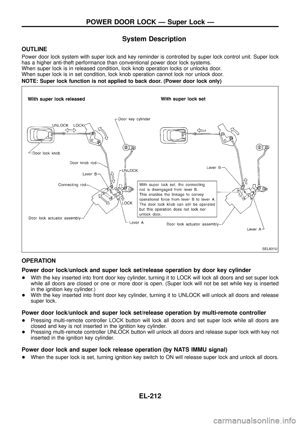
System Description
OUTLINE
Power door lock system with super lock and key reminder is controlled by super lock control unit. Super lock
has a higher anti-theft performance than conventional power door lock systems.
When super lock is in released condition, lock knob operation locks or unlocks door.
When super lock is in set condition, lock knob operation cannot lock nor unlock door.
NOTE: Super lock function is not applied to back door. (Power door lock only)
OPERATION
Power door lock/unlock and super lock set/release operation by door key cylinder
+With the key inserted into front door key cylinder, turning it to LOCK will lock all doors and set super lock
while all doors are closed or one or more door is open. (Super lock will not be set while key is inserted
in the ignition key cylinder.)
+With the key inserted into front door key cylinder, turning it to UNLOCK will unlock all doors and release
super lock.
Power door lock/unlock and super lock set/release operation by multi-remote controller
+Pressing multi-remote controller LOCK button will lock all doors and set super lock while all doors are
closed and key is not inserted in the ignition key cylinder.
+Pressing multi-remote controller UNLOCK button will unlock all doors and release super lock with key not
inserted in the ignition key cylinder.
Power door lock and super lock release operation (by NATS IMMU signal)
+When the super lock is set, turning ignition key switch to ON will release super lock and unlock all doors.
SEL831U
POWER DOOR LOCK Ð Super Lock Ð
EL-212