1998 NISSAN PATROL Trans
[x] Cancel search: TransPage 7 of 326
Description
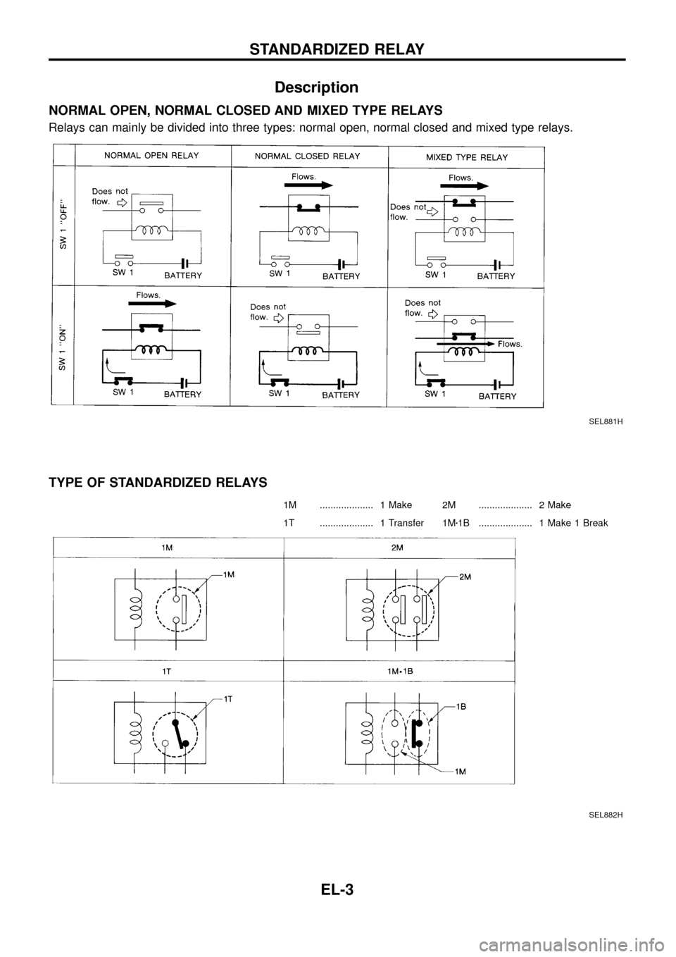
NORMAL OPEN, NORMAL CLOSED AND MIXED TYPE RELAYS
Relays can mainly be divided into three types: normal open, normal closed and mixed type relays.
TYPE OF STANDARDIZED RELAYS
1M .................... 1 Make 2M .................... 2 Make
1T .................... 1 Transfer 1Mz1B .................... 1 Make 1 Break
SEL881H
SEL882H
STANDARDIZED RELAY
EL-3
Page 69 of 326
System Description
OPERATION
Headlamp system on vehicles for North Europe contains a daytime light system. The unit operates to illumi-
nate headlamps low beam, parking, tail, license lamps and illuminations automatically in the following condi-
tions.
+The engine is running with lighting switch in OFF position.
When the any of following conditions exists, the daytime light operation will be canceled.
+Ignition switch is in any position other than ON
+Engine is stopped
+Lighting switch is turned to 1st or 2nd position.
If the daytime light system is canceled, lighting switch operations are the same as for conventional light sys-
tem.
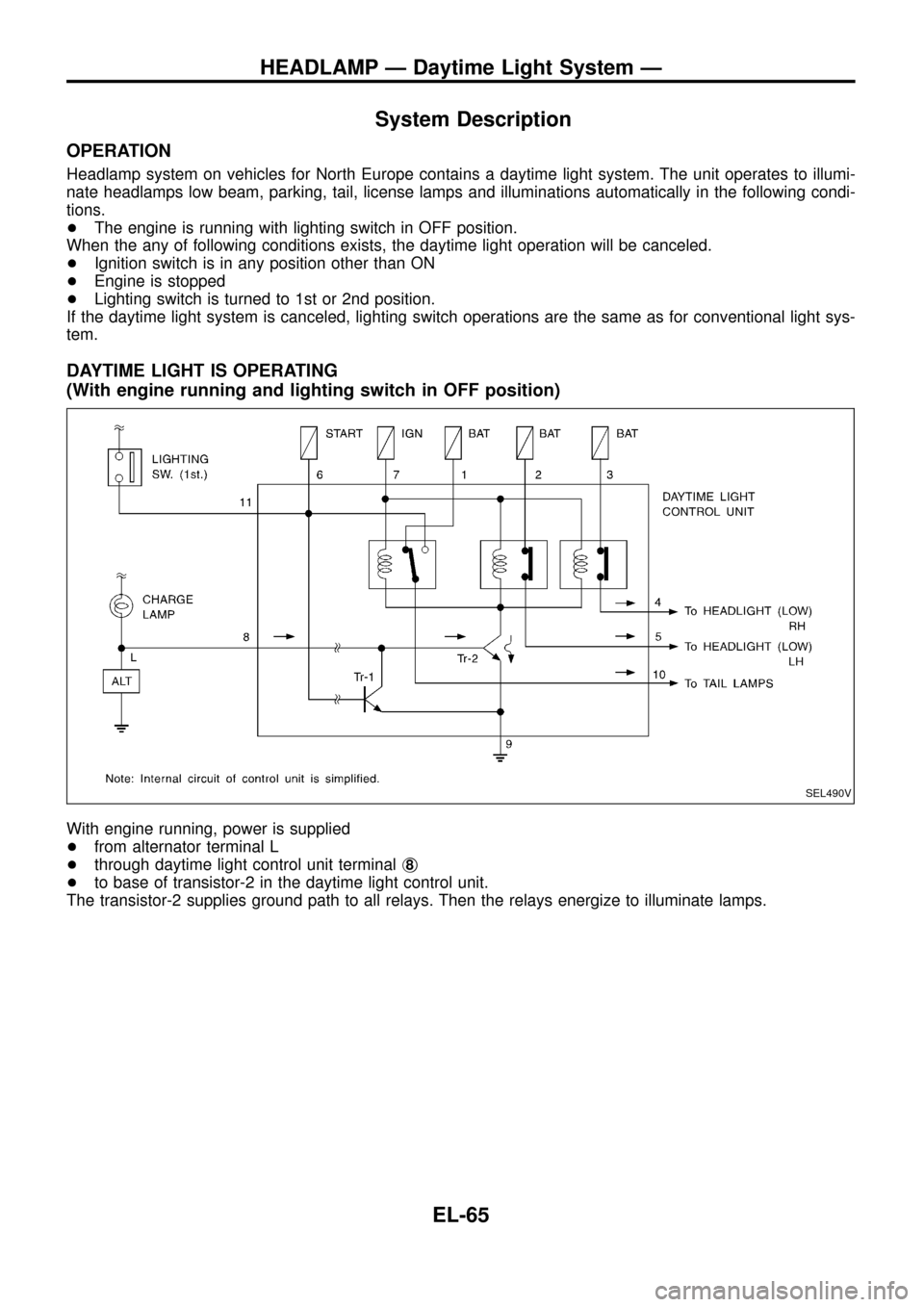
DAYTIME LIGHT IS OPERATING
(With engine running and lighting switch in OFF position)
With engine running, power is supplied
+from alternator terminal L
+through daytime light control unit terminalj
8
+to base of transistor-2 in the daytime light control unit.
The transistor-2 supplies ground path to all relays. Then the relays energize to illuminate lamps.
SEL490V
HEADLAMP Ð Daytime Light System Ð
EL-65
Page 70 of 326
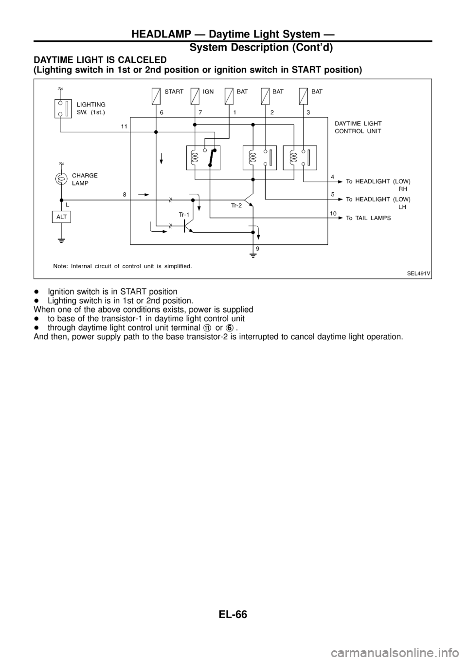
DAYTIME LIGHT IS CALCELED
(Lighting switch in 1st or 2nd position or ignition switch in START position)
+Ignition switch is in START position
+Lighting switch is in 1st or 2nd position.
When one of the above conditions exists, power is supplied
+to base of the transistor-1 in daytime light control unit
+through daytime light control unit terminalj
11orj6.
And then, power supply path to the base transistor-2 is interrupted to cancel daytime light operation.
SEL491V
HEADLAMP Ð Daytime Light System Ð
System Description (Cont'd)
EL-66
Page 115 of 326
SYMPTOM CHART
Symptom chart 1 (Malfunction is indicated in Diagnosis mode)
Symptom Possible causes Repair order
Speedometer and/or odo/trip
meter indicate(s) malfunction
in Diagnosis mode.+Speedometer (Uni®ed meter control unit)+Replace speedometer (uni®ed meter control unit).
Multiple meter/gauge indicate
malfunction in Diagnosis
mode.
One of tachometer/fuel gauge/
water temp. gauge indicates
malfunction in Diagnosis
mode.+Meter/Gauge
+Speedometer (Uni®ed meter control unit)1. Check resistance of meter/gauge indicating malfunction. If
the resistance is NG, replace the meter/gauge. Refer to
``METER/GAUGE RESISTANCE CHECK'', EL-114.
2. If the resistance is OK, replace speedometer (uni®ed meter
control unit).
Symptom chart 2 (No malfunction is indicated in Diagnosis mode)
Symptom Possible causes Repair order
Speedometer and odo/trip
meter are malfunctioning.1. Sensor
- Speedometer, Odo/Trip meter
2. FPC connector
3. Speedometer (Uni®ed meter control unit)1. Check vehicle speed sensor.
INSPECTION/VEHICLE SPEED SENSOR (Refer to EL-112.)
2. Check FPC connector. Refer to ``Flexible Print Circuit
(FPC)'', EL-109.
3. Replace speedometer (uni®ed meter control unit).
Multiple meter/gauge are mal-
functioning. (except
speedometer, odo/trip meter)1. FPC connector
2. Speedometer (Uni®ed meter control unit)1. Check FPC connector. Refer to ``Flexible Print Circuit
(FPC)'', EL-109.
2. Replace speedometer (uni®ed meter control unit).
One of tachometer/fuel gauge/
water temp. gauge is malfunc-
tioning.1. Sensor/Engine revolution signal
- Tachometer
- Fuel gauge
- Water temp. gauge
2. FPC connector
3. Speedometer (Uni®ed meter control unit)1. Check the sensor for malfunctioning meter/gauge.
INSPECTION/ENGINE REVOLUTION SIGNAL (Refer to
EL-113.)
INSPECTION/FUEL TANK GAUGE (Refer to EL-113.)
INSPECTION/THERMAL TRANSMITTER (Refer to EL-114.)
2. Check FPC connector. Refer to ``Flexible Print Circuit
(FPC)'', EL-109.
3. Replace speedometer (uni®ed meter control unit).
Before starting trouble diagnoses above, perform PRELIMINARY CHECK, EL-110.
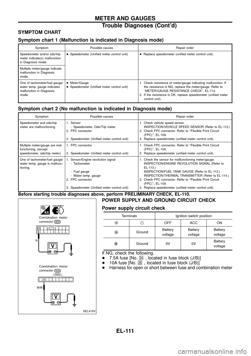
POWER SUPPLY AND GROUND CIRCUIT CHECK
Power supply circuit check
Terminals Ignition switch position
Å@OFF ACC ON
j
33GroundBattery
voltageBattery
voltageBattery
voltage
j
9Ground 0V 0VBattery
voltage
If NG, check the following.
+7.5A fuse [No.
24, located in fuse block (J/B)]
+10A fuse [No.
28, located in fuse block (J/B)]
+Harness for open or short between fuse and combination meter
SEL419V
METER AND GAUGES
Trouble Diagnoses (Cont'd)
EL-111
Page 116 of 326
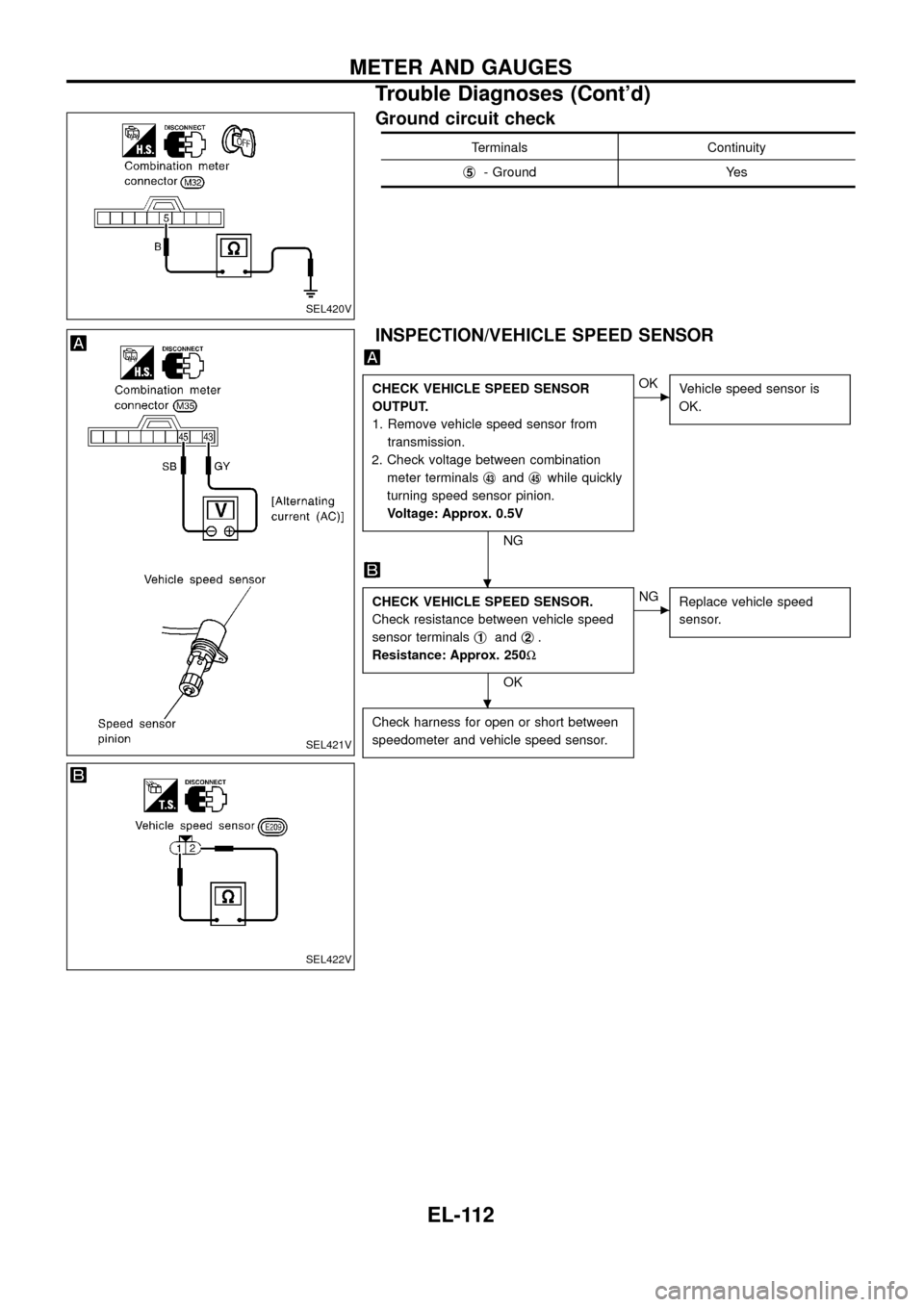
Ground circuit check
Terminals Continuity
j
5- Ground Yes
INSPECTION/VEHICLE SPEED SENSOR
CHECK VEHICLE SPEED SENSOR
OUTPUT.
1. Remove vehicle speed sensor from
transmission.
2. Check voltage between combination
meter terminalsj
43andj45while quickly
turning speed sensor pinion.
Voltage: Approx. 0.5V
NG
cOK
Vehicle speed sensor is
OK.
CHECK VEHICLE SPEED SENSOR.
Check resistance between vehicle speed
sensor terminalsj
1andj2.
Resistance: Approx. 250W
OK
cNG
Replace vehicle speed
sensor.
Check harness for open or short between
speedometer and vehicle speed sensor.
SEL420V
SEL421V
SEL422V
.
.
METER AND GAUGES
Trouble Diagnoses (Cont'd)
EL-112
Page 118 of 326
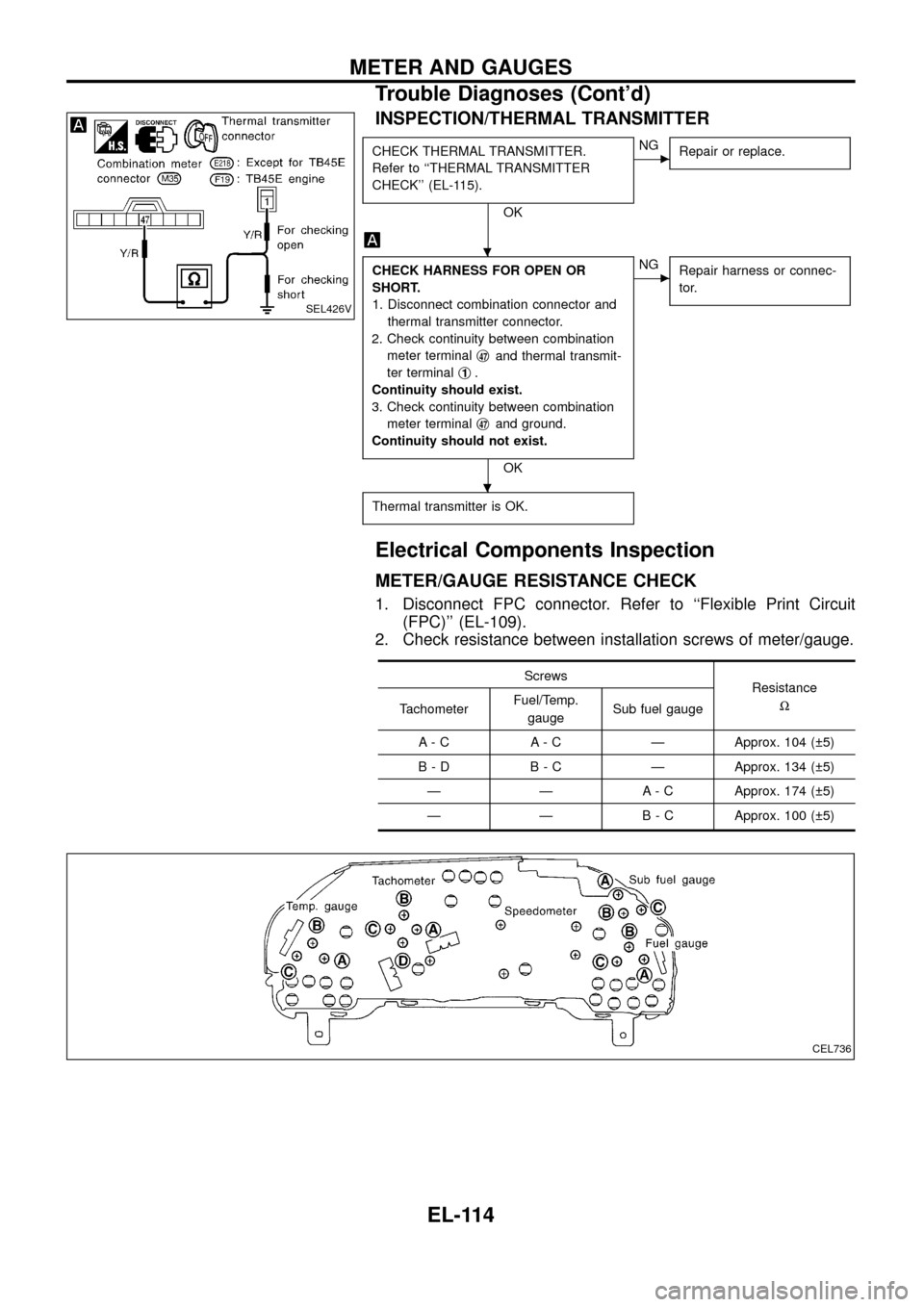
INSPECTION/THERMAL TRANSMITTER
CHECK THERMAL TRANSMITTER.
Refer to ``THERMAL TRANSMITTER
CHECK'' (EL-115).
OK
cNG
Repair or replace.
CHECK HARNESS FOR OPEN OR
SHORT.
1. Disconnect combination connector and
thermal transmitter connector.
2. Check continuity between combination
meter terminalj
47and thermal transmit-
ter terminalj
1.
Continuity should exist.
3. Check continuity between combination
meter terminalj
47and ground.
Continuity should not exist.
OK
cNG
Repair harness or connec-
tor.
Thermal transmitter is OK.
Electrical Components Inspection
METER/GAUGE RESISTANCE CHECK
1. Disconnect FPC connector. Refer to ``Flexible Print Circuit
(FPC)'' (EL-109).
2. Check resistance between installation screws of meter/gauge.
Screws
Resistance
W
TachometerFuel/Temp.
gaugeSub fuel gauge
A - C A - C Ð Approx. 104 ( 5)
B - D B - C Ð Approx. 134 ( 5)
Ð Ð A - C Approx. 174 ( 5)
Ð Ð B - C Approx. 100 ( 5)
SEL426V
CEL736
.
.
METER AND GAUGES
Trouble Diagnoses (Cont'd)
EL-114
Page 119 of 326
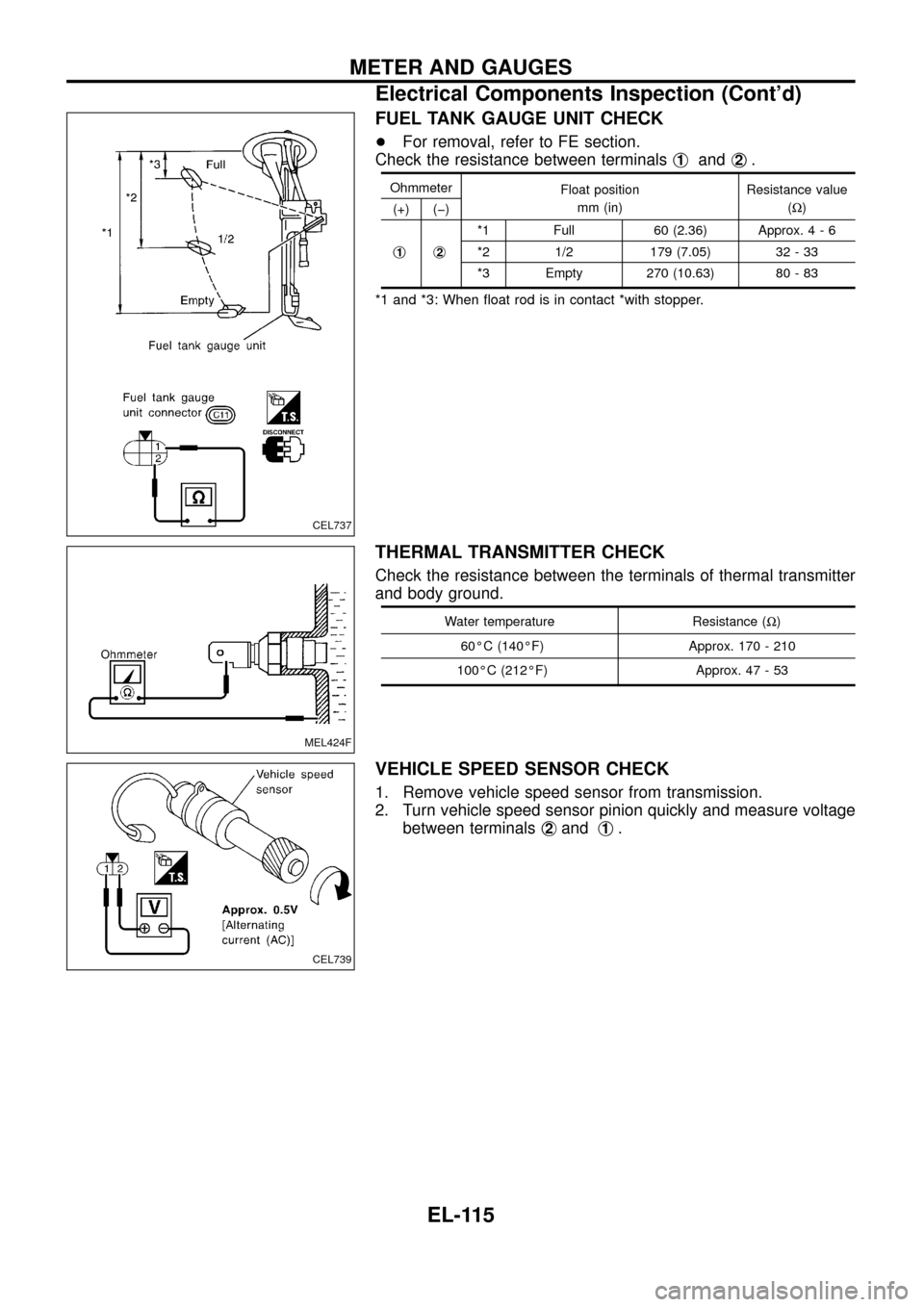
FUEL TANK GAUGE UNIT CHECK
+For removal, refer to FE section.
Check the resistance between terminalsj
1andj2.
Ohmmeter
Float position
mm (in)Resistance value
(W)
(+) (þ)
j
1j2
*1 Full 60 (2.36) Approx.4-6
*2 1/2 179 (7.05) 32 - 33
*3 Empty 270 (10.63) 80 - 83
*1 and *3: When ¯oat rod is in contact *with stopper.
THERMAL TRANSMITTER CHECK
Check the resistance between the terminals of thermal transmitter
and body ground.
Water temperature Resistance (W)
60ÉC (140ÉF) Approx. 170 - 210
100ÉC (212ÉF) Approx. 47 - 53
VEHICLE SPEED SENSOR CHECK
1. Remove vehicle speed sensor from transmission.
2. Turn vehicle speed sensor pinion quickly and measure voltage
between terminalsj
2andj1.
CEL737
MEL424F
CEL739
METER AND GAUGES
Electrical Components Inspection (Cont'd)
EL-115
Page 178 of 326
NATS Audio Link/LHD
DESCRIPTION
The link with the NATS IMMU implies that the radio can basically only be operated if connected to the match-
ing NATS IMMU to which the radio was initially ®tted on the production line.
Since radio operation is impossible after the link with the NATS is disrupted theft of the radio unit is basically
useless since special equipment is required to reset the radio.
Initialisation process for radios that are linked to the NATS IMMU
New radios will be delivered to the factories in the ``NEW'' state, i.e. ready to be linked with the vehicle's NATS.
When the radio in ``NEW'' state is ®rst switched on at the factory, it will start up communication with the vehi-
cle's immobiliser control unit (IMMU) and send a code (the ``Radio Code'') to the IMMU. The IMMU will then
store this code, which is unique to each radio, in its (permanent) memory.
Upon receipt of the code by the IMMU, the NATS will con®rm correct receipt of the radio code to the radio.
Hereafter, the radio will operate as normal.
During the initialisation process, ``NEW'' is displayed on the radio display. Normally though, communication
between Radio and IMMU takes such a short time (300 ms) that the radio seems to switch on directly with-
out showing ``NEW'' on its display.
Normal operation
Each time the radio is switched on afterwards, the radio code will be veri®ed between the radio unit and the
NATS before the radio becomes operational. During the code veri®cation process, ``WAIT'' is shown on the
radio display. Again, the communication takes such a short time (300 ms) that the radio seems to switch on
directly without showing ``WAIT'' on its display.
When the radio is locked
In case of a radio being linked with the vehicle's NATS (immobiliser system), disconnection of the link between
the radio and the IMMU will cause the radio to switch into the lock (``SECURE'') mode in which the radio unit
is fully inoperative. Hence, repair of the radio is basically impossible, unless the radio is reset to the ``NEW''
state for which special decoding equipment is required.
Both Blaupunkt and Clarion have provided their authorized service representatives with so called ``decoder
boxes'' which can bring the radio unit back to the ``NEW'' state, enabling the radio to be switched on after which
repair can be carried out. Subsequently, when the repaired radio is delivered to the ®nal user again, it will be
in the ``NEW'' state as to enable re-linking the radio to the vehicle's immobiliser system. As a result of the
above, repair of the radio can only be done by an authorized Blaupunkt or Clarion representative.
Note:
Radio manufacturer of Nissan Y61 models for Europe is ``Clarion''.
SERVICE PROCEDURE
Item Service procedure Description
Battery disconnection No additional action required. Ð
Radio needs repair Repair needs to be done by authorized represen-
tative of radio manufacturer since radio cannot
be operated unless it is reset to NEW state,
using special decoding equipment.Ð
Replacement of radio by new
partNo additional action required. Radio is delivered in NEW state.
Transferring radio to another
vehicle/replacement of radio
by an ``old'' partRadio needs to be reset to NEW state by autho-
rized representative of radio manufacturer.Ð
Replacement of IMMU by
new partNo additional action required. The new IMMU will be recognized by the radio
since a `blank' code is stored in the memory of
the IMMU. In case the radio recognizes this
`blank' code, it will request for input of the correct
CATS code after which the radio will switch back
to the initialisation process.
AUDIO
EL-174