Page 233 of 326
DIAGNOSTIC PROCEDURE 4
[Super lock actuator (in door lock actuator assembly)
check]
CHECK OUTPUT SIGNAL FOR SUPER
LOCK ACTUATOR.
Check voltage for super lock actuator.
Put the system in set condition before
checking release signal.
Refer to wiring diagram in EL-215 (LHD),
EL-219 (RHD).
OK
cNG
Super lock actuator is OK.
CHECK SUPER LOCK ACTUATOR.
1. Disconnect door lock actuator assembly
connector.
2. Set lever A in Lock position.
3. Apply 12V direct current to door lock
actuator assembly and check operation.
NG
cOK
Check harness between
control unit and door lock
actuator assembly.
Replace door lock actuator assembly.
Door key cylinder
switch conditionTerminals
Voltage
(V)
Å@Lock (Set)j18Ground
Approx. 12
Unlock
(Released)j
13Ground
Super lock actua-
tor operationTerminals
Connection from
lever B to lever A
Å@Released®Setj1j4Disconnect
Set®Releasedj
4j1Connect
SEL819UB
SEL820UB
.
.
POWER DOOR LOCK Ð Super Lock Ð
Trouble Diagnoses (Cont'd)
EL-229
Page 234 of 326
DIAGNOSTIC PROCEDURE 5
(Door switch check)
CHECK DOOR SWITCH INPUT SIGNAL.
Check voltage between control unit termi-
nalj
8and ground.
Refer to wiring diagram in EL-215 (LHD),
EL-219 (RHD).
NG
cOK
Door switch is OK.
CHECK DOOR SWITCH.
1. Disconnect door switch connector.
2. Check continuity between door switch
terminals.
OK
cNG
Replace door switch.
Check the following.
+Door switch ground condition
+Harness for open or short between con-
trol unit and door switch
Condition Voltage [V]
Any door is opened. 0
All doors are closed. Approx. 12
Terminals Condition Continuity
Driver side
door
switchj
2-
groundClosed No
Open Yes
Other door
switchesj
1-
groundClosed No
Open Yes
SEL821UB
SEL822UC
.
.
POWER DOOR LOCK Ð Super Lock Ð
Trouble Diagnoses (Cont'd)
EL-230
Page 235 of 326
DIAGNOSTIC PROCEDURE 6
(NATS release signal check)
Does engine start properly?
Ye s
cNo
Check NATS system.
CHECK NATS SIGNAL CIRCUIT.
1. Disconnect control unit connector and
NATS IMMU connector.
2. Check continuity between control unit
terminalj
9and NATS IMMU terminal
j
3(LHD models),j7(RHD models).
Continuity should exist.
3. Check continuity between control unit
terminalj
9and ground.
Continuity should not exist.
Refer to wiring diagram in EL-215
(LHD), EL-219 (RHD).
OK
cNG
Repair harness.
CHECK NATS RELEASE SIGNAL.
1. Connect control unit connector and
NATS IMMU connector.
2. Check voltage between control unit ter-
minalj
9and ground.
OK
cNG
Check NATS system.
Replace super lock control unit.
Ignition switch conditionVoltage
[V]
OFF
5
More than 10 seconds after ignition
switch turned ON
For 10 seconds after ignition switch
turned ONPulse
SEL493V
SEL494V
SEL495V
.
.
.
POWER DOOR LOCK Ð Super Lock Ð
Trouble Diagnoses (Cont'd)
EL-231
Page 236 of 326

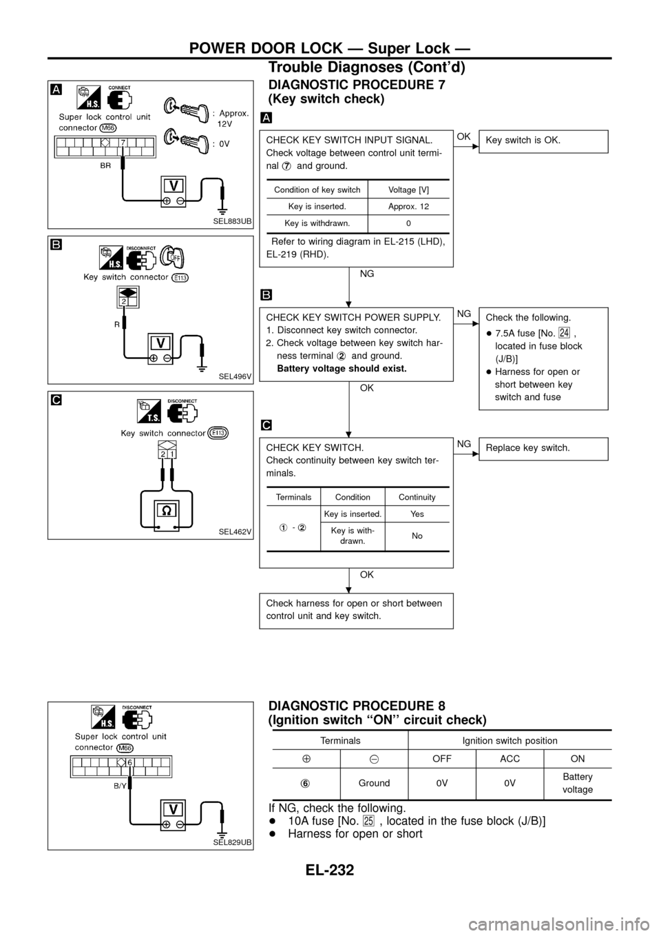
DIAGNOSTIC PROCEDURE 7
(Key switch check)
CHECK KEY SWITCH INPUT SIGNAL.
Check voltage between control unit termi-
nalj
7and ground.
Refer to wiring diagram in EL-215 (LHD),
EL-219 (RHD).
NG
cOK
Key switch is OK.
CHECK KEY SWITCH POWER SUPPLY.
1. Disconnect key switch connector.
2. Check voltage between key switch har-
ness terminalj
2and ground.
Battery voltage should exist.
OK
cNG
Check the following.
+7.5A fuse [No.
24,
located in fuse block
(J/B)]
+Harness for open or
short between key
switch and fuse
CHECK KEY SWITCH.
Check continuity between key switch ter-
minals.
OK
cNG
Replace key switch.
Check harness for open or short between
control unit and key switch.
Condition of key switch Voltage [V]
Key is inserted. Approx. 12
Key is withdrawn. 0
Terminals Condition Continuity
j
1-j2
Key is inserted. Yes
Key is with-
drawn.No
DIAGNOSTIC PROCEDURE 8
(Ignition switch ``ON'' circuit check)
Terminals Ignition switch position
Å@OFF ACC ON
j
6Ground 0V 0VBattery
voltage
If NG, check the following.
+10A fuse [No.
25, located in the fuse block (J/B)]
+Harness for open or short
SEL883UB
SEL496V
SEL462V
SEL829UB
.
.
.
POWER DOOR LOCK Ð Super Lock Ð
Trouble Diagnoses (Cont'd)
EL-232
Page 237 of 326
DIAGNOSTIC PROCEDURE 9
(Remote controller signal check)
CHECK REMOTE CONTROLLER INPUT
SIGNAL.
1. Withdraw key from ignition key cylinder.
2. Check voltage between control unit ter-
minalj
2orj3and ground.
NOTE: The multi-remote control system
does not activate with key inserted
in ignition key cylinder or if one of
the doors is opened.
Refer to Wiring Diagram in EL-216.
NG
cOK
Replace super lock control
unit.
Check harness for open or short between
super lock control unit and multi-remote
control unit.
TerminalsCondition of
remote controller
buttonVoltage
[V]
Å@
j
2GroundLOCK button is
pressed0 (Approx.
0.5 seconds)
LOCK button is
released5
j
3GroundUNLOCK button
is pressed0 (Approx.
0.5 seconds)
UNLOCK button
is released5
SEL051VA
.
POWER DOOR LOCK Ð Super Lock Ð
Trouble Diagnoses (Cont'd)
EL-233
Page 238 of 326

System Description
FUNCTION
Multi-remote control system has the following function.
+Door lock (and set super lock)
+Door unlock (and release super lock)
+Hazard reminder
LOCK OPERATION
To lock door by multi-remote controller, the following two signals must be received.
+Key switch OFF (when ignition key is not in ignition key cylinder.)
+All door switches CLOSED
When the LOCK signal is input to multi-remote control unit (the antenna of the system is combined with multi-
remote control unit), ground is supplied
+through multi-remote control unit terminalj
10
+to super lock control unit terminalj2.
Then super lock control unit operates to lock doors and set super lock.
UNLOCK OPERATION
To unlock door by multi-remote controller, the following signal must be received.
+Key switch OFF (when ignition key is not in ignition key cylinder)
When the UNLOCK signal is input to multi-remote control unit (the antenna of the system is combined with
multi-remote control unit), ground is supplied
+through multi-remote control unit terminalj
11
+to super lock control unit terminalj3.
Then super lock control unit operates to unlock doors and release super lock.
HAZARD REMINDER
When the doors are locked or unlocked by multi-remote controller, ground is supplied
+to terminalj
1of multi-remote control relay-1 and 2
+through multi-remote control unit terminalj
12.
Then the relays are energized and hazard warning lamp ¯ashes as follows
+Lock operation: Flash once
+Unlock operation: Flash twice
MULTI-REMOTE CONTROLLER ID CODE ENTRY
A maximum of four remote controllers can be entered. Any attempt to enter a remote controller will erase all
ID codes previously entered. Therefore, be sure to receive all remote controllers from the vehicle owner when
any ID code entry is performed.
To enter ID code entry, the following signals must be input to the multi-remote control unit.
+Driver side LOCKED signal (from driver side door unlock sensor)
+Door switch CLOSED signal
+Key switch signal (INSERTED/WITHDRAWN)
+Accessory power supply
+Signal from remote controller
For detailed procedure, refer to ``ID Code Entry Procedure'' in EL-239.
MULTI-REMOTE CONTROL SYSTEM
EL-234
Page 239 of 326
Wiring Diagram Ð MULTI Ð/LHD Models
TEL688A
MULTI-REMOTE CONTROL SYSTEM
EL-235
Page 240 of 326
TEL689A
MULTI-REMOTE CONTROL SYSTEM
Wiring Diagram Ð MULTI Ð/LHD Models
(Cont'd)
EL-236