1998 NISSAN PATROL Automatic
[x] Cancel search: AutomaticPage 69 of 326
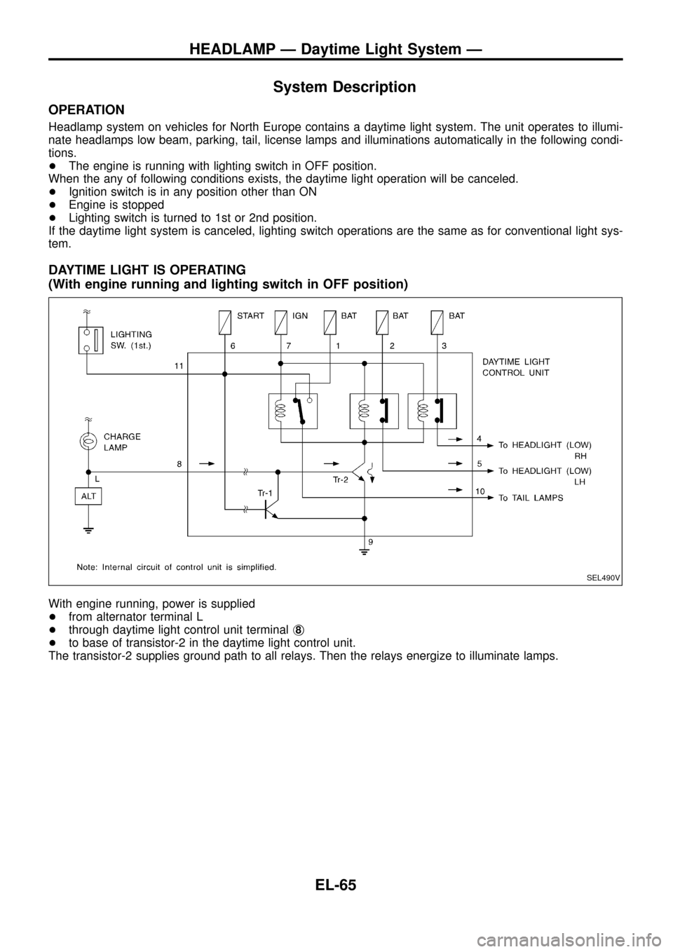
System Description
OPERATION
Headlamp system on vehicles for North Europe contains a daytime light system. The unit operates to illumi-
nate headlamps low beam, parking, tail, license lamps and illuminations automatically in the following condi-
tions.
+The engine is running with lighting switch in OFF position.
When the any of following conditions exists, the daytime light operation will be canceled.
+Ignition switch is in any position other than ON
+Engine is stopped
+Lighting switch is turned to 1st or 2nd position.
If the daytime light system is canceled, lighting switch operations are the same as for conventional light sys-
tem.
DAYTIME LIGHT IS OPERATING
(With engine running and lighting switch in OFF position)
With engine running, power is supplied
+from alternator terminal L
+through daytime light control unit terminalj
8
+to base of transistor-2 in the daytime light control unit.
The transistor-2 supplies ground path to all relays. Then the relays energize to illuminate lamps.
SEL490V
HEADLAMP Ð Daytime Light System Ð
EL-65
Page 123 of 326
a) The temperature detected by the ambient air temperature sensor is lower than the indicated tem-
perature on the thermometer.
b) The difference in temperature detected during a period of 40 seconds is less than 1ÉC (1.8ÉF) when
vehicle speed has been greater than 24 km/h (15 MPH) for more than 100 seconds.
(This is to prevent the indicated temperature from being affected by engine heat or cooling fan
operation during low-speed driving.)
c) The ignition key has been turned to the ``OFF'' position for more than 4 hours. (The engine is cold.)
Calibration Procedure For Compass
The difference between magnetic North and geographical North
can sometimes be great enough to cause false compass readings.
In order for the compass to operate accurately in a particular zone,
it must be calibrated using the following procedure.
1. Determine your location on the worldwide magnetic variation
map on next page. Record your zone number.
2. Turn the ignition switch to ACC or ON position.
3. Push the ``Mode'' switch continuously for ®ve seconds until the
current zone entry number is displayed.
4. Press the ``Mode'' switch repeatedly until the desired zone num-
ber is displayed.
Once the desired zone number is displayed, stop pressing the
``Mode'' switch and the display will show compass direction after a
few seconds.
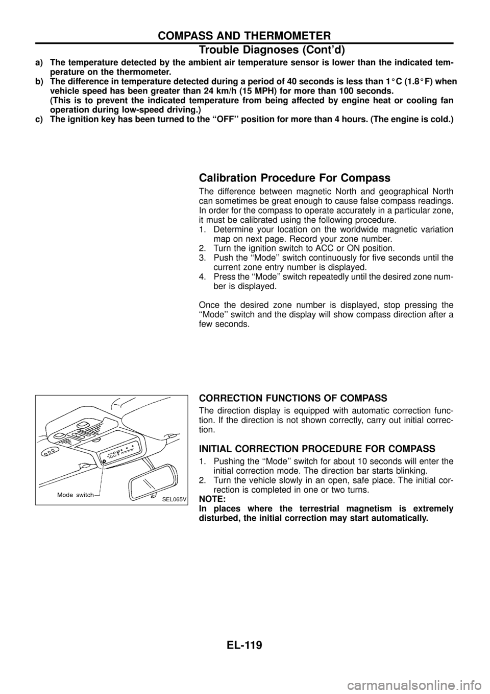
CORRECTION FUNCTIONS OF COMPASS
The direction display is equipped with automatic correction func-
tion. If the direction is not shown correctly, carry out initial correc-
tion.
INITIAL CORRECTION PROCEDURE FOR COMPASS
1. Pushing the ``Mode'' switch for about 10 seconds will enter the
initial correction mode. The direction bar starts blinking.
2. Turn the vehicle slowly in an open, safe place. The initial cor-
rection is completed in one or two turns.
NOTE:
In places where the terrestrial magnetism is extremely
disturbed, the initial correction may start automatically.
SEL065V
COMPASS AND THERMOMETER
Trouble Diagnoses (Cont'd)
EL-119
Page 177 of 326
CATS (Code) System/RHD
NOTE:
+This system is used for code indicator-equipped radios on all models except the Europe LHD
model.
+The Europe LHD model has a NATS-linked anti-theft function that renders the code system inop-
erable.
DESCRIPTION
By using a personal 4-digit code known only to the vehicle owner, the possibility of the audio unit being sto-
len is effectively reduced, because without the code the unit can not be activated. When in normal use, the
unit is unlocked and accessible in the usual way.
If however, someone attempts to remove the unit or the battery cable is disconnected, the anti-theft system
activates and the unit ``locks''. The only way it can be unlocked is by entering a personal code number known
only by the owner.
UNLOCKING THE UNIT (How to enter a personal code number)
+If the battery supply to the vehicle is interrupted by accident for some reason, the unit will lock.
To unlock the unit, proceed as follows:
1. Press the power/volume control knob to turn the unit on.
2. ``CODE IN'' is displayed.
3. Input your personal code by pressing the preset buttons (1 to 4).
4. Press the
button.
5. If the entered code number is correct, the radio turns on.
When the code is incorrect
1. If the entered code is incorrect, the unit becomes inoperable for 10 seconds for the ®rst three attempts,
then the code input mode is automatically set (``CODE IN'' is displayed).
2. If the code is incorrect the fourth time, the unit becomes inoperable for 60 minutes and ``
'' is displayed.
After 60 minutes, the code input mode is automatically set (``CODE IN'' is displayed).
NOTE:
If the above is repeated 17 times, the unit will lock and ``LOCKED'' is displayed.
3. After ``LOCKED'' is displayed, radio can be returned to the code input mode only within three attempts as
follows. (Only three attempts are allowed to unlock the unit.)
a. Press the power/volume control knob while pushing both the MOD and TA switches.
b. The unit then returns to the code input mode.
CAUTION:
If the third attempt is unsuccessful, the unit will lock permanently.
AUDIO
EL-173
Page 244 of 326
System Description
NATS has the following immobiliser functions:
+Since only NATS ignition keys, whose ID nos. have been registered into the ECM and IMMU of NATS,
allow the engine to run, operation of a stolen vehicle without a NATS registered key is prevented by NATS.
That is to say, NATS will immobilize the engine if someone tries to start it without the registered key of
NATS.
+Both of the originally supplied ignition key IDs have been NATS registered.
If requested by the vehicle owner, a maximum of four key IDs can be registered into the NATS compo-
nents.
+The NATS security indicator (NATS security ind.) blinks when the ignition switch is in ``OFF'' or ``ACC''
position. Therefore, NATS warns outsiders that the vehicle is equipped with the anti-theft system.
+When NATS detects trouble, the malfunction indicator lamp (MIL) blinks.
+NATS trouble diagnoses, system initialisation and additional registration of other NATS ignition key IDs
must be carried out using CONSULT hardware and CONSULT NATS software.
When NATS initialisation has been completed, the ID of the inserted ignition key is automatically NATS
registered. Then, if necessary, additional registration of other NATS ignition key IDs can be carried out.
Regarding the procedures of NATS initialisation and NATS ignition key ID registration, refer to CONSULT
operation manual, NATS.
+When servicing a malfunction of the NATS (indicated by ¯ashing of Malfunction Indicator Lamp)
or registering another NATS ignition key ID no., it may be necessary to re-register original key
identi®cation. Therefore, be sure to receive all keys from vehicle owner.
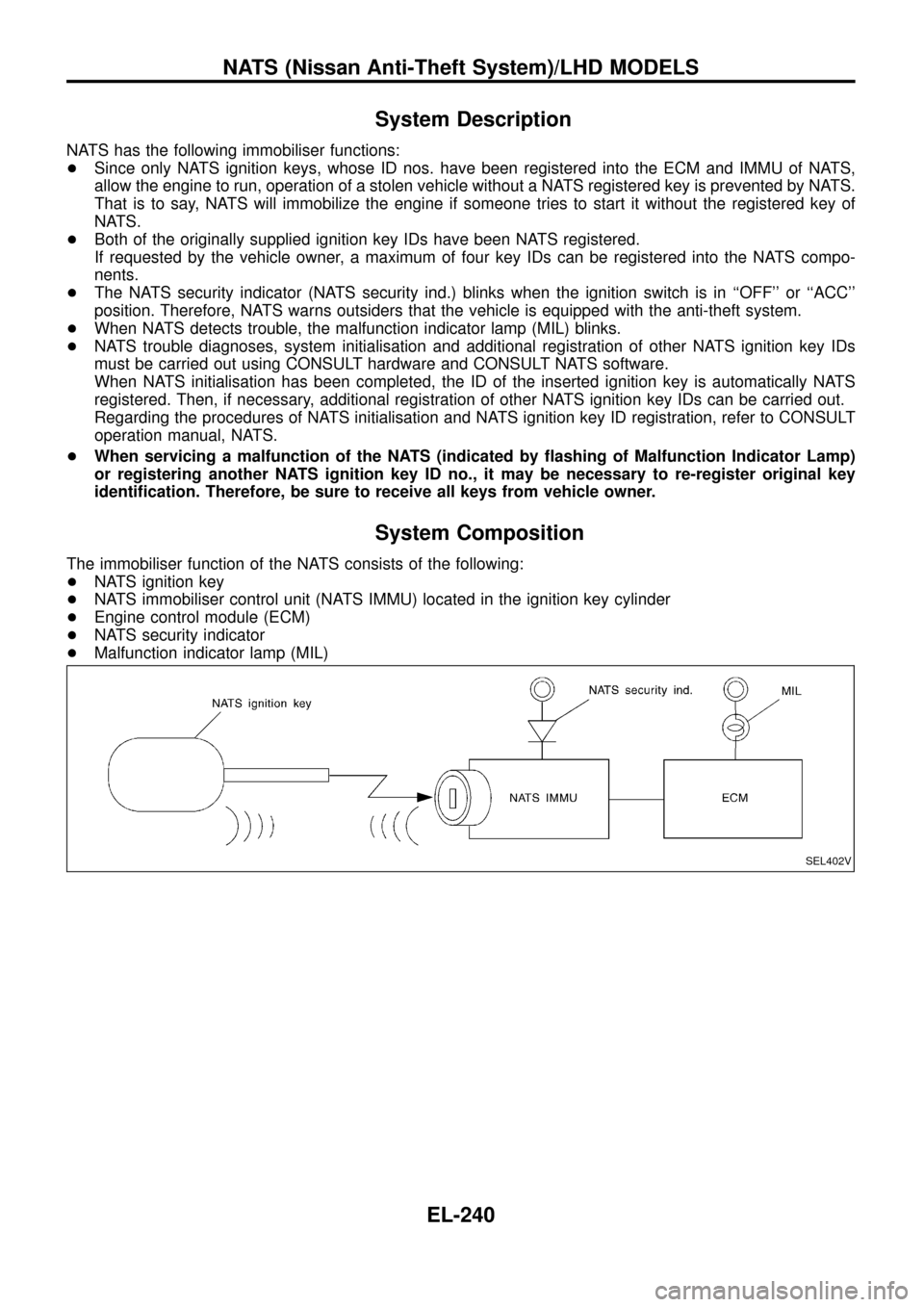
System Composition
The immobiliser function of the NATS consists of the following:
+NATS ignition key
+NATS immobiliser control unit (NATS IMMU) located in the ignition key cylinder
+Engine control module (ECM)
+NATS security indicator
+Malfunction indicator lamp (MIL)
SEL402V
NATS (Nissan Anti-Theft System)/LHD MODELS
EL-240
Page 259 of 326
System Description
NATS has the following immobiliser functions:
+Since only NATS ignition keys, whose ID nos. have been registered into the ECM and IMMU of NATS,
allow the engine to run, operation of a stolen vehicle without a NATS registered key is prevented by NATS.
That is to say, NATS will immobilize the engine if someone tries to start it without the registered key of
NATS.
+Both of the originally supplied ignition key IDs have been NATS registered.
If requested by the vehicle owner, a maximum of four key IDs can be registered into the NATS compo-
nents.
+The NATS security indicator (NATS security ind.) blinks when the ignition switch is in ``OFF'' or ``ACC''
position. Therefore, NATS warns outsiders that the vehicle is equipped with the anti-theft system.
+When NATS detects trouble, the malfunction indicator lamp (MIL) blinks.
+NATS trouble diagnoses, system initialisation and additional registration of other NATS ignition key IDs
must be carried out using CONSULT hardware and CONSULT NATS software.
When NATS initialisation has been completed, the ID of the inserted ignition key is automatically NATS
registered. Then, if necessary, additional registration of other NATS ignition key IDs can be carried out.
Regarding the procedures of NATS initialisation and NATS ignition key ID registration, refer to CONSULT
operation manual, NATS.
+When servicing a malfunction of the NATS (indicated by ¯ashing of Malfunction Indicator Lamp)
or registering another NATS ignition key ID no., it may be necessary to re-register original key
identi®cation. Therefore, be sure to receive all keys from vehicle owner.
System Composition
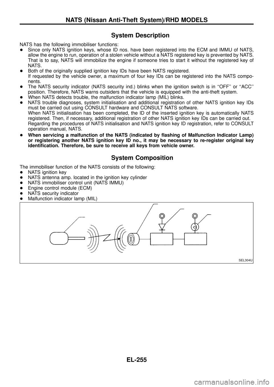
The immobiliser function of the NATS consists of the following:
+NATS ignition key
+NATS antenna amp. located in the ignition key cylinder
+NATS immobiliser control unit (NATS IMMU)
+Engine control module (ECM)
+NATS security indicator
+Malfunction indicator lamp (MIL)
SEL304U
NATS (Nissan Anti-Theft System)/RHD MODELS
EL-255
Page 319 of 326
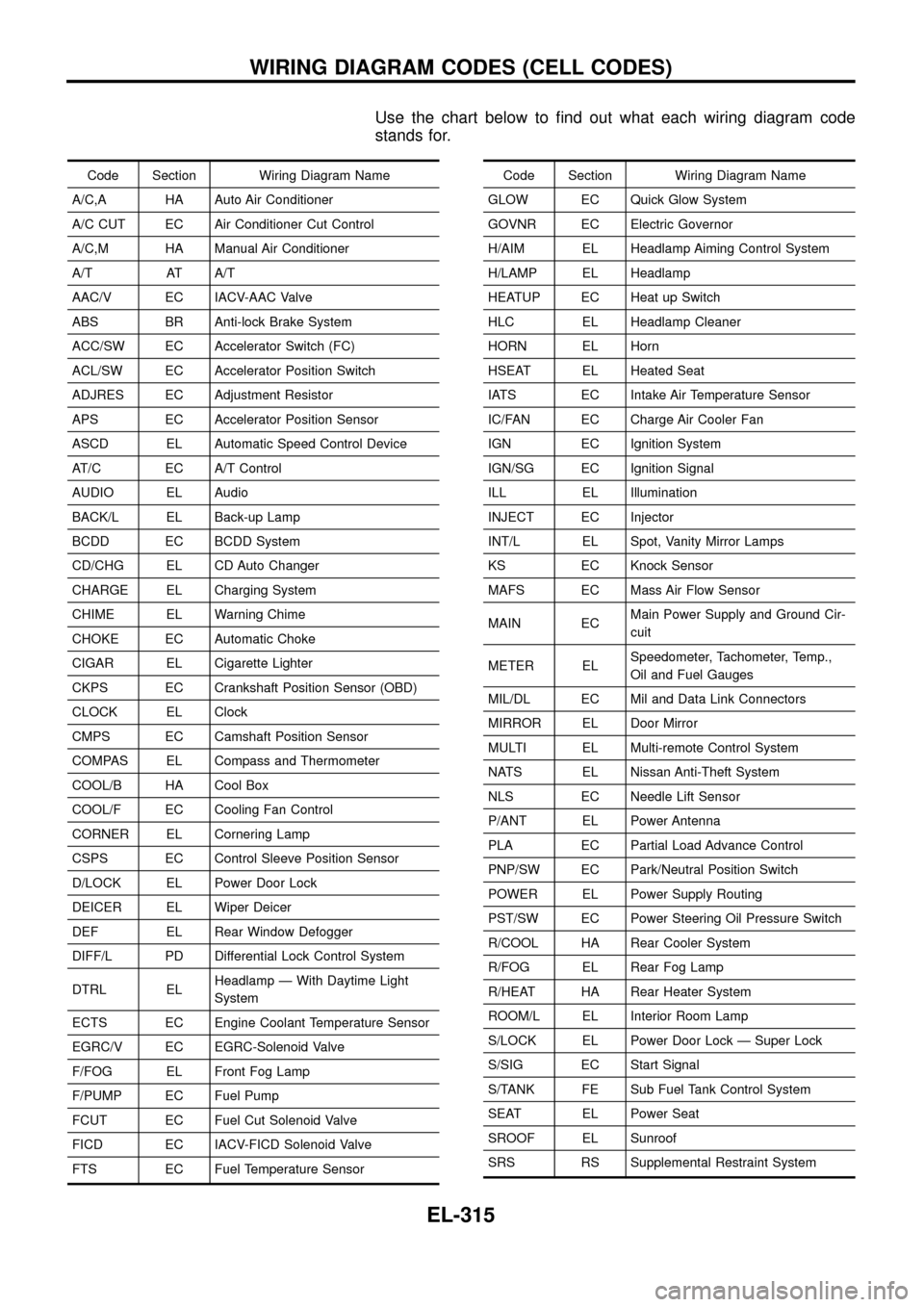
Use the chart below to ®nd out what each wiring diagram code
stands for.
Code Section Wiring Diagram Name
A/C,A HA Auto Air Conditioner
A/C CUT EC Air Conditioner Cut Control
A/C,M HA Manual Air Conditioner
A/T AT A/T
AAC/V EC IACV-AAC Valve
ABS BR Anti-lock Brake System
ACC/SW EC Accelerator Switch (FC)
ACL/SW EC Accelerator Position Switch
ADJRES EC Adjustment Resistor
APS EC Accelerator Position Sensor
ASCD EL Automatic Speed Control Device
AT/C EC A/T Control
AUDIO EL Audio
BACK/L EL Back-up Lamp
BCDD EC BCDD System
CD/CHG EL CD Auto Changer
CHARGE EL Charging System
CHIME EL Warning Chime
CHOKE EC Automatic Choke
CIGAR EL Cigarette Lighter
CKPS EC Crankshaft Position Sensor (OBD)
CLOCK EL Clock
CMPS EC Camshaft Position Sensor
COMPAS EL Compass and Thermometer
COOL/B HA Cool Box
COOL/F EC Cooling Fan Control
CORNER EL Cornering Lamp
CSPS EC Control Sleeve Position Sensor
D/LOCK EL Power Door Lock
DEICER EL Wiper Deicer
DEF EL Rear Window Defogger
DIFF/L PD Differential Lock Control System
DTRL ELHeadlamp Ð With Daytime Light
System
ECTS EC Engine Coolant Temperature Sensor
EGRC/V EC EGRC-Solenoid Valve
F/FOG EL Front Fog Lamp
F/PUMP EC Fuel Pump
FCUT EC Fuel Cut Solenoid Valve
FICD EC IACV-FICD Solenoid Valve
FTS EC Fuel Temperature SensorCode Section Wiring Diagram Name
GLOW EC Quick Glow System
GOVNR EC Electric Governor
H/AIM EL Headlamp Aiming Control System
H/LAMP EL Headlamp
HEATUP EC Heat up Switch
HLC EL Headlamp Cleaner
HORN EL Horn
HSEAT EL Heated Seat
IATS EC Intake Air Temperature Sensor
IC/FAN EC Charge Air Cooler Fan
IGN EC Ignition System
IGN/SG EC Ignition Signal
ILL EL Illumination
INJECT EC Injector
INT/L EL Spot, Vanity Mirror Lamps
KS EC Knock Sensor
MAFS EC Mass Air Flow Sensor
MAIN ECMain Power Supply and Ground Cir-
cuit
METER ELSpeedometer, Tachometer, Temp.,
Oil and Fuel Gauges
MIL/DL EC Mil and Data Link Connectors
MIRROR EL Door Mirror
MULTI EL Multi-remote Control System
NATS EL Nissan Anti-Theft System
NLS EC Needle Lift Sensor
P/ANT EL Power Antenna
PLA EC Partial Load Advance Control
PNP/SW EC Park/Neutral Position Switch
POWER EL Power Supply Routing
PST/SW EC Power Steering Oil Pressure Switch
R/COOL HA Rear Cooler System
R/FOG EL Rear Fog Lamp
R/HEAT HA Rear Heater System
ROOM/L EL Interior Room Lamp
S/LOCK EL Power Door Lock Ð Super Lock
S/SIG EC Start Signal
S/TANK FE Sub Fuel Tank Control System
SEAT EL Power Seat
SROOF EL Sunroof
SRS RS Supplemental Restraint System
WIRING DIAGRAM CODES (CELL CODES)
EL-315