Page 191 of 396
Tool A25
(MB990991)Tool B28
(MB990992)Tool C31
MB990925
Brass bar
Bar (on")
REAR AXLE – Special Tools / Troubleshooting 27-5
MB990988NumberNameO.D. mm
1MB990551Box–
2MB990989Base–
3(MB990990)Tool A25
(MB990991)Tool B28
(MB990992)Tool C31
MB990925
Brass bar
Bar (one-touch type)Toolbox
Installer adapter
Tool number (MB990925)O.D. mmTool number (MB990925)O.D. mm
AMB99092639.0AMB99093363.5
MB99092745.0MB99093467.5
MB99092849.5MB99093571.5
MB99092951.0MB99093675.5
MB99093054.0MB99093779.0
MB99093157.0BMB990938–
MB99093261.0CMB990939–
TROUBLESHOOTING
1. BASIC TROUBLESHOOTING CONDITIONS
Before starting the troubleshooting procedure, make sure that the following items have been checked
okay.
�The correct steering wheel has been properly installed in the neutral position of the steering column
shaft.
�Tire and wheel sizes are correct with correct specifications. Inflation pressure, balance, and wear
conditions are okay.
�Wheel alignment is correct.
�The engine, suspension, and other parts have not been remodeled so as to affect the AYC system.
2. DIAGNOSIS FUNCTION
READING THE DIAGNOSIS CODE
Read the diagnosis code using AYC warning lamp.
Page 216 of 396
 After the system has been completely bled of air, check
for the fluid level.
Caution
If the system is not completely bled of air, the hydr")
REAR AXLE – On-vehicle Service 27-30
(7) After the system has been completely bled of air, check
for the fluid level.
Caution
If the system is not completely bled of air, the hydraulic
unit could generate noise, degrading pump durability.
6. DIFFERENTIAL CARRIER OIL SEAL
REPLACEMENT
6-1 DIFFERENTIAL
(1) Remove the drive shaft. (Refer to p. 27-36.)
(2) Remove the oil seal from the differential carrier.
(3) Using the special tool, drive a new oil seal all the way
into position.
(4) Coat the oil seal lips and the drive shaft surface in contact
with the oil seal with multi-purpose grease.
(5) Replace the drive shaft circlip with a new one and mount
the drive shaft to the differential carrier. (Refer to P.27-36.)
(6) Check for correct wheel alignment. (Refer to GROUP
34 – On-vehicle Service.)
6-2 TORQUE TRANSFER MECHANISM
(1) Remove the drive shaft. (Refer to p. 27-36.)
(2) Remove the oil seal from the differential carrier.
(3) Using the special tool, drive a new oil seal all the way
into position.
(4) Coat the oil seal lips and the drive shaft surface in contact
with the oil seal with the specified grease.
Specified grease: Vaseline
(5) Replace the drive shaft circlip with a new one and mount
the drive shaft to the differential carrier. (Refer to P.27-36.)
(6) Check for correct wheel alignment. (Refer to GROUP
34 – On-vehicle Service.)MB990938
MB991115
MD998829
MD998812
MD998813
Page 222 of 396
 Gear Oil Draining (Refer to P.27-28.)
(2) Center Exhaust Pipe Removal
(Refer to GROUP 15.)Post-installati")
REAR AXLE – Drive Shaft27-36
DRIVE SHAFT
REMOVAL AND INSTALLATION
Pre-removal Operation
(1) Gear Oil Draining (Refer to P.27-28.)
(2) Center Exhaust Pipe Removal
(Refer to GROUP 15.)Post-installation Operation
(1) Checking Each Ball Joint Dust Cover for Cracks
and Damages by Pressing Dust Cover with Finger
(2) Center Exhaust Pipe Installation
(Refer to GROUP 15.)
(3) Gear Oil Filling (Refer to P.27-28.)
(4) Parking Brake Lever Stroke Check and Adjustment
(Refer to GROUP 36 – On-vehicle Service.)
(5) Wheel Alignment Check and Adjustment
(Refer to GROUP 34 – On-vehicle Service.)
1
2 3
4
56 7
89 10 11
Unit: Nm {kgf�m}
25 {2.6}
74 – 87 {7.5 – 8.9}
74 – 87
{7.5 – 8.9}*88 {9.0}* 49 – 59 {5.0 – 6.0}
196 – 255 {20.0 – 26.0}
Removal steps
1. Caliper assembly
(Refer to P.27-33.)
2. Brake disc
3. Shoe & lining assembly (Refer to
GROUP 36 – Parking Brake.)
4. Clip
5. Parking brake cable connection
�A��B�6. Drive shaft nut
7. Rear speed sensor coupling
8. Trailing arm coupling
9. Lower arm coupling
10. Toe control arm coupling
�B��A�11. Drive shaftCaution
(1) With the part marked with *, first temporarily
tighten it, then ground the vehicle and tighten
it to specification in unloaded condition.
(2) When removing the drive shaft from, and
reinstalling it to, a vehicle with AYC, use care
not to damage the rotor mounted on the BJ outer
race.
Page 242 of 396
33A-1
FRONT
SUSPENSION
CONTENTS
SERVICE SPECIFICATIONS 2. . . . . . . . . . . . . .
SPECIAL TOOLS 2. . . . . . . . . . . . . . . . . . . . . . . .
ON-VEHICLE SERVICE 3. . . . . . . . . . . . . . . . . .
Wheel Alignment Check and Adjustment
3. . . . . . . . . . . . . . . . . . . . . . . . .
STRUT ASSEMBLY 4. . . . . . . . . . . . . . . . . . . . . .
LOWER ARM 5. . . . . . . . . .
LOWER ARM 7. . . . . . . . . . .
STABILIZER BAR 9. . . . . . . . . . . . . . . . . . . . . . . .
Page 244 of 396
FRONT SUSPENSION – On-vehicle Service33A-3
ON-VEHICLE SERVICE
WHEEL ALIGNMENT CHECK AND
ADJUSTMENT
Use the conventional procedures to measure wheel alignment.
1. CAMBER
Standard value:
–1�00’ ± 30’ (difference between right and left
wheel: less than 30’) or
–2�00’ ± 30’ (difference between right and left
wheel: less than 30’)
Select the camber angle as follows.
If the arrow on the bolt that couples the strut assembly
to knuckle faces inboard → –1�00’ ± 30’.
If the arrow on the bolt that couples the strut assembly
to knuckle faces outboard → –2�00’ ± 30’.
2. CASTER
Standard value: 3�54’ ± 30’ (difference between right
and left wheel: less than 30’)
NOTE
The suspension system is designed so as to retain the
preset caster value, requiring no adjustment for caster.
Bolt coupling strut
assembly to
knuckle
Page 245 of 396
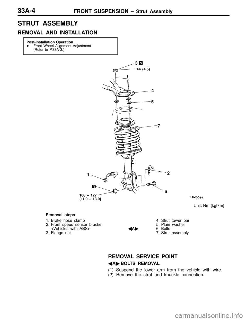
FRONT SUSPENSION – Strut Assembly33A-4
STRUT ASSEMBLY
REMOVAL AND INSTALLATION
Post-installation Operation
�Front Wheel Alignment Adjustment
(Refer to P.33A-3.)
12 3
4
5
6 7
Unit: Nm {kgf�m}
44 {4.5}
108 – 127
{11.0 – 13.0}
Removal steps
1. Brake hose clamp
2. Front speed sensor bracket
3. Flange nut4. Strut tower bar
5. Plain washer
�A�6. Bolts
7. Strut assembly
REMOVAL SERVICE POINT
�A�BOLTS REMOVAL
(1) Suspend the lower arm from the vehicle with wire.
(2) Remove the strut and knuckle connection.
Page 246 of 396
FRONT SUSPENSION – Lower Arm 33A-5
LOWER ARM
REMOVAL AND INSTALLATION
Post-installation Operation
(1) Push the Dust Cover of the Lower Arm and Stabilizer
Link Ball Joint with a Finger to Check for Possible
Cracks or Damage.
(2) Wheel Alignment Check and Adjustment
12
3
45
6
Unit: Nm {kgf�m}
39 {4.0}113 {11.5}
Molybdenum disulfide-base chassis
grease:
SHOWA SHELL SEKIYU SUNLITE
MB2, NISSEKI CLAKNOCK FL, or
equivalent
137 {14.0}
88 {9.0} 106 {10.8}*
6
Removal steps
1. Stabilizer link mounting nut
�A�2. Lower arm to knuckle coupling bolt
3. Bolt
4. Stabilizer bracket
�A�5. Bushing assembly
6. Lower arm assemblyCaution
The part marked with * should be first temporarily
tightened, then torqued to specification with the
vehicle on the ground in unloaded condition.
NOTE
Follow the conventional procedures for removal service
points.
Page 248 of 396
FRONT SUSPENSION – Lower Arm 33A-7
LOWER ARM
REMOVAL AND INSTALLATION
Caution
To prevent bushing from being galled, the part
marked with * should be first temporarily tightened,
then torqued to specification with the vehicle on
the ground in unloaded condition.Post-installation Operation
(1) Push the Dust Cover of the Lower Arm and Stabilizer
Link Ball Joint with a Finger to Check for Possible
Cracks or Damage.
(2) Wheel Alignment Check and Adjustment
(Refer to P.33A-3.)
12
3
456
Unit: Nm {kgf�m} Molybdenum disulfide-base chassis
grease:
SHOWA SHELL SEKIYU SUNLITE
MB2, NISSEKI CLAKNOCK FL, or
equivalent
39 {4.0}108 {11.0}
137 {14.0}
88 {9.0} 106 {10.8}*
6
Removal steps
1. Stabilizer link mounting nut
�A��B�2. Lower arm to knuckle coupling bolt
3. Bolt
4. Stabilizer bracket
�A�5. Bushing assembly
6. Lower arm assemblyNOTE
Follow the conventional procedures for removal service
points.


 Push the Dust Cover of the Lower Arm and Stabilizer
Link Ball Joint")
