Page 22 of 396

ENGINE – Crankshaft Oil Seal11-16
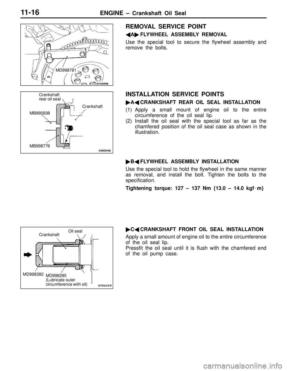
REMOVAL SERVICE POINT
�A�FLYWHEEL ASSEMBLY REMOVAL
Use the special tool to secure the flywheel assembly and
remove the bolts.
INSTALLATION SERVICE POINTS
�A�CRANKSHAFT REAR OIL SEAL INSTALLATION
(1) Apply a small mount of engine oil to the entire
circumference of the oil seal lip.
(2) Install the oil seal with the special tool as far as the
chamfered position of the oil seal case as shown in the
illustration.
�B�FLYWHEEL ASSEMBLY INSTALLATION
Use the special tool to hold the flywheel in the same manner
as removal, and install the bolt. Tighten the bolts to the
specification.
Tightening torque: 127 – 137 Nm {13.0 – 14.0 kgf�m}
�C�CRANKSHAFT FRONT OIL SEAL INSTALLATION
Apply a small amount of engine oil to the entire circumference
of the oil seal lip.
Pressfit the oil seal until it is flush with the chamfered end
of the oil pump case.
MD998781
Crankshaft
rear oil seal
MB990938
MB998776Crankshaft
Crankshaft
MD998382
Oil seal
MD998285
(Lubricate outer
circumference with oil)
Page 128 of 396
MANUAL TRANSMISSION – Transmission Assembly22A-8
16 18
Unit: Nm {kgf�m}
52 {5.3}*
19
17
9
10
12
1315
1214
69 {7.0} 69 {7.0} 15 – 33
{1.5 – 3.4} 39 {4.0}59 – 71
{6.0 – 7.2} 26 – 33
{2.7 – 3.4}48 {4.9}
52 {5.3}*
Lifting up of the vehicle
9. Stabilizer bar connection
10. Wheel speed sensor cable connec-
tion
11. Brake hose clamp
12. Tie rod end connection
13. Lower arm ball joint connection
�A��Clutch release bearing connection
14. Centermember assembly
�B�15. Drive shaft connection
�B�16. Drive shaft connection
�Strut assembly
(Refer to GROUP 33A.)�C�17. Output shaft
�Air hose A
(Refer to GROUP 15 – Intercooler.)
18. Transmission assembly lower part
coupling bolts
19. Transmission assembly
Caution
Mounting locations marked by * should be
provisionally tightened, and then fully tightened
when the body is supporting the full weight of the
engine.
Page 245 of 396
FRONT SUSPENSION – Strut Assembly33A-4
STRUT ASSEMBLY
REMOVAL AND INSTALLATION
Post-installation Operation
�Front Wheel Alignment Adjustment
(Refer to P.33A-3.)
12 3
4
5
6 7
Unit: Nm {kgf�m}
44 {4.5}
108 – 127
{11.0 – 13.0}
Removal steps
1. Brake hose clamp
2. Front speed sensor bracket
3. Flange nut4. Strut tower bar
5. Plain washer
�A�6. Bolts
7. Strut assembly
REMOVAL SERVICE POINT
�A�BOLTS REMOVAL
(1) Suspend the lower arm from the vehicle with wire.
(2) Remove the strut and knuckle connection.
Page 308 of 396
STEERING –
Steering Wheel /
Power Steering Gear & Linkage37A-3
STEERING WHEEL
REMOVAL SERVICE POINT
STEERING WHEEL REMOVAL
(1) Peel off the dual lock fasteners from the steering wheel
spokes and remove the horn pad.
(2) Remove the bolts indicated by arrows in the illustration
and remove the steering wheel from the boss plate.
(3) Using the special tool, remove the boss plate from the
steering column.
POWER STEERING GEAR &
LINKAGE
For removal, installation and inspection procedure, follow the
conventional procedures except the following.
INSPECTION
PINION TOTAL TURNING TORQUE
The conventional procedures apply except for the standard
value.
Standard value:
Total turning torque 0.9 to 1.7 Nm {9 to 17 kgf�cm}
Torque fluctuations 0.4 Nm {4 kgf�cm} or less
Dual lock
fastener
Boss plate
MB990803