Page 36 of 396

ENGINE – Timing Belt11-30
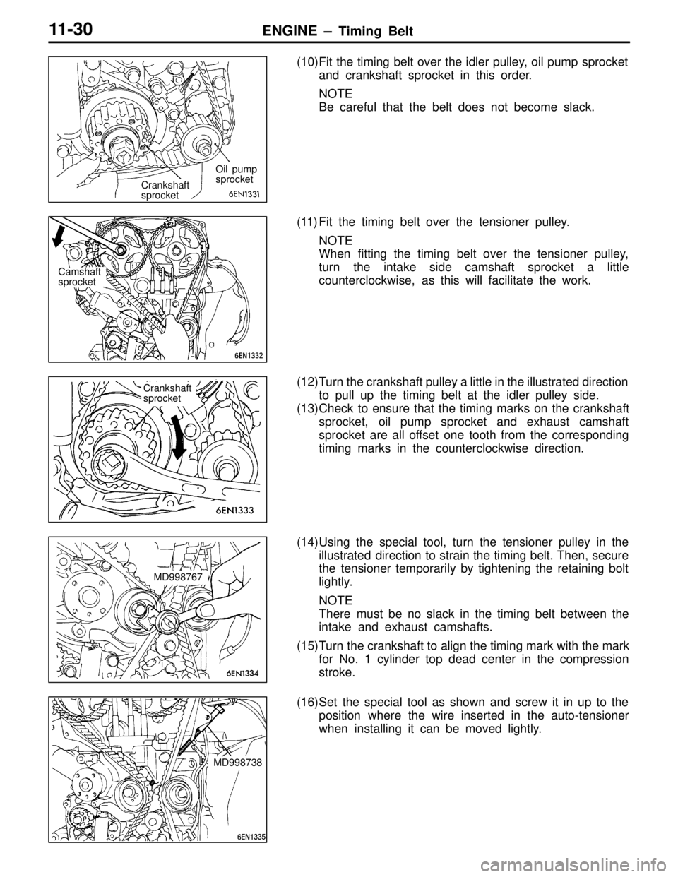
(10)Fit the timing belt over the idler pulley, oil pump sprocket
and crankshaft sprocket in this order.
NOTE
Be careful that the belt does not become slack.
(11) Fit the timing belt over the tensioner pulley. NOTE
When fitting the timing belt over the tensioner pulley,
turn the intake side camshaft sprocket a little
counterclockwise, as this will facilitate the work.
(12)Turn the crankshaft pulley a little in the illustrated direction to pull up the timing belt at the idler pulley side.
(13)Check to ensure that the timing marks on the crankshaft sprocket, oil pump sprocket and exhaust camshaft
sprocket are all offset one tooth from the corresponding
timing marks in the counterclockwise direction.
(14)Using the special tool, turn the tensioner pulley in the illustrated direction to strain the timing belt. Then, secure
the tensioner temporarily by tightening the retaining bolt
lightly.
NOTE
There must be no slack in the timing belt between the
intake and exhaust camshafts.
(15)Turn the crankshaft to align the timing mark with the mark for No. 1 cylinder top dead center in the compression
stroke.
(16)Set the special tool as shown and screw it in up to the position where the wire inserted in the auto-tensioner
when installing it can be moved lightly.
Crankshaft
sprocket Oil pump
sprocket
Camshaft
sprocket
Crankshaft
sprocket
MD998767
MD998738
Page 37 of 396

ENGINE – T iming Belt 11-31
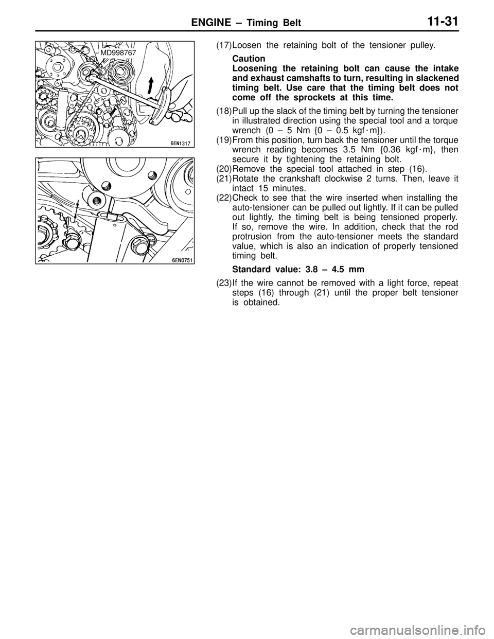
(17)Loosen the retaining bolt of the tensioner pulley.
Caution
Loosening the retaining bolt can cause the intake
and exhaust camshafts to turn, resulting in slackened
timing belt. Use care that the timing belt does not
come off the sprockets at this time.
(18)Pull up the slack of the timing belt by turning the tensioner in illustrated direction using the special tool and a torque
wrench (0 – 5 Nm {0 – 0.5 kgf �m}).
(19)From this position, turn back the tensioner until the torque wrench reading becomes 3.5 Nm {0.36 kgf �m}, then
secure it by tightening the retaining bolt.
(20)Remove the special tool attached in step (16).
(21)Rotate the crankshaft clockwise 2 turns. Then, leave it intact 15 minutes.
(22)Check to see that the wire inserted when installing the
auto-tensioner can be pulled out lightly. If it can be pulled
out lightly, the timing belt is being tensioned properly.
If so, remove the wire. In addition, check that the rod
protrusion from the auto-tensioner meets the standard
value, which is also an indication of properly tensioned
timing belt.
Standard value: 3.8 – 4.5 mm
(23)If the wire cannot be removed with a light force, repeat steps (16) through (21) until the proper belt tensioner
is obtained.MD998767
Page 85 of 396
ENGINE COOLING – Water Pump14-5
WATER PUMP
REMOVAL AND INSTALLATION
Pre-removal and Post-installation Operation
�Engine Coolant Draining and Supplying
(Refer to P.14-2.)�Timing Belt and Timing Belt B Removal and Installation
(Refer to GROUP 11.)
12 – 15 {1.2 – 1.5} 24 {2.4}
8 × 22 8 × 14
Bolt specifications
8 × 24
Screw diameter × length mm
1
2
4
3
2
22 {2.2}
8 × 70
Unit: Nm {kgf�m}
Removal steps
1. Alternator brace
2. Water pump
3. Water pump gasket
�A�4. O-ring
INSTALLATION SERVICE POINT
�A�O-RING INSTALLATION
Fit the O-ring in the O-ring groove in the water inlet pipe,
and coat the outer circumference of the O-ring or the inside
surface of the water pump with water before inserting the
pipe.
Water pump
O-ring
Water inlet pipe
Page 108 of 396
ENGINE ELECTRICAL – Ignition System16-5
CAMSHAFT POSITION SENSOR AND CRANK ANGLE SENSOR
REMOVAL AND INSTALLATION
Pre-removal and Post-installation Operation
�Timing Belt Removal and Installation
(Refer to GROUP 11.)
Unit: Nm {kgf�m}
49 {5.0}
5
9 {0.9}9 {0.9}
9 {0.9} 39 {4.0} 3 {0.3}
2
3
41
Removal steps
1. Camshaft position sensor
2. Center cover
�A�3. Power steering oil pump4. Power steering oil pump bracket
5. Crank angle sensor
REMOVAL SERVICE POINT
�A�POWER STEERING OIL PUMP REMOVAL
Remove the power steering oil pump with hose from the power
steering oil pump bracket.
NOTE
String up the oil pump which has been removed onto a location
that does not hamper removal and installation of the power
steering oil pump bracket.
Page:
< prev 1-8 9-16 17-24