Page 14 of 396

ENGINE – Engine Adjustments11-8
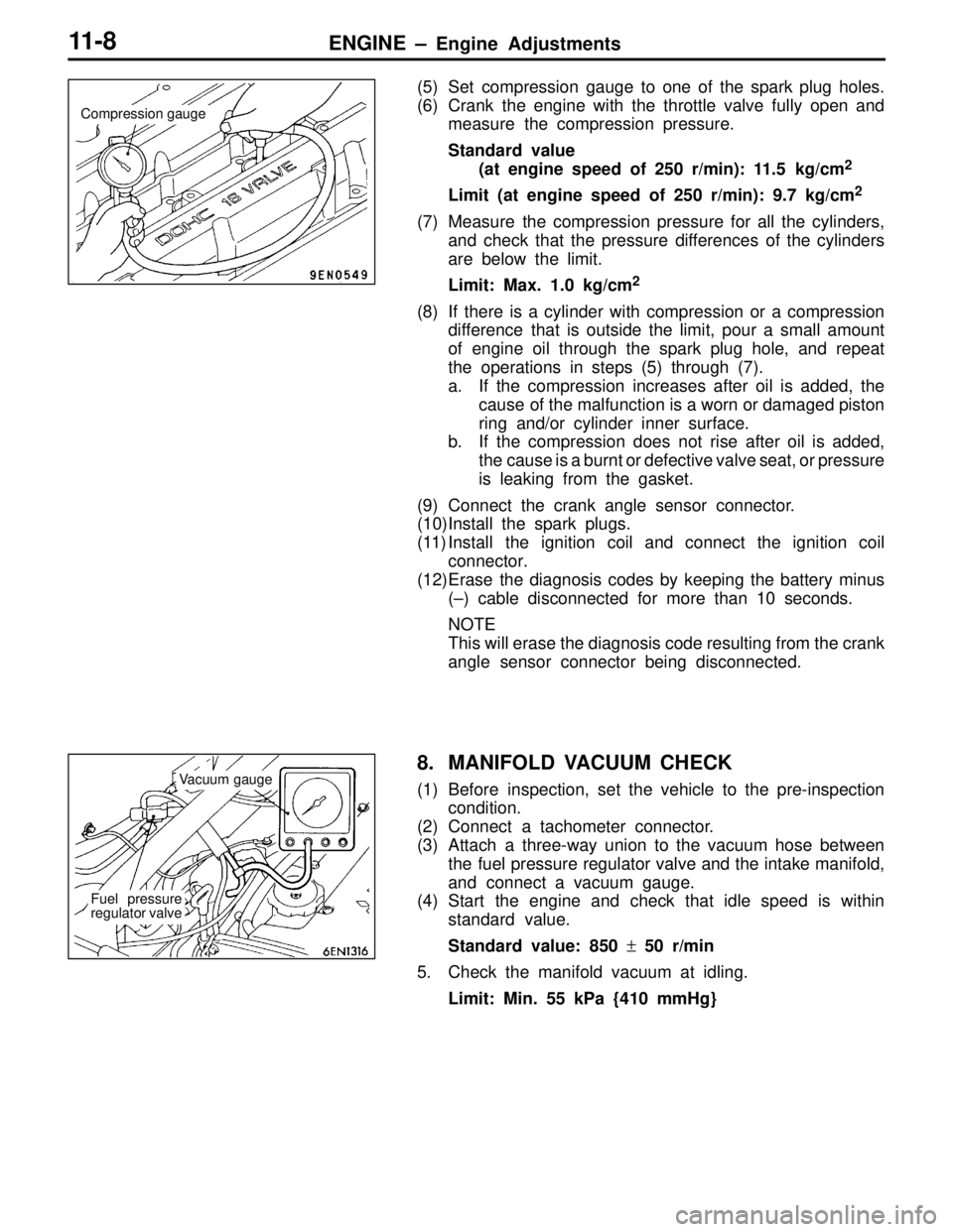
(5) Set compression gauge to one of the spark plug holes.
(6) Crank the engine with the throttle valve fully open and
measure the compression pressure.
Standard value
(at engine speed of 250 r/min): 11.5 kg/cm
2
Limit (at engine speed of 250 r/min): 9.7 kg/cm2
(7) Measure the compression pressure for all the cylinders,
and check that the pressure differences of the cylinders
are below the limit.
Limit: Max. 1.0 kg/cm
2
(8) If there is a cylinder with compression or a compression
difference that is outside the limit, pour a small amount
of engine oil through the spark plug hole, and repeat
the operations in steps (5) through (7).
a. If the compression increases after oil is added, the
cause of the malfunction is a worn or damaged piston
ring and/or cylinder inner surface.
b. If the compression does not rise after oil is added,
the cause is a burnt or defective valve seat, or pressure
is leaking from the gasket.
(9) Connect the crank angle sensor connector.
(10)Install the spark plugs.
(11) Install the ignition coil and connect the ignition coil
connector.
(12)Erase the diagnosis codes by keeping the battery minus
(–) cable disconnected for more than 10 seconds.
NOTE
This will erase the diagnosis code resulting from the crank
angle sensor connector being disconnected.
8. MANIFOLD VACUUM CHECK
(1) Before inspection, set the vehicle to the pre-inspection
condition.
(2) Connect a tachometer connector.
(3) Attach a three-way union to the vacuum hose between
the fuel pressure regulator valve and the intake manifold,
and connect a vacuum gauge.
(4) Start the engine and check that idle speed is within
standard value.
Standard value: 850 ± 50 r/min
5. Check the manifold vacuum at idling.
Limit: Min. 55 kPa {410 mmHg}
Compression gauge
Vacuum gauge
Fuel pressure
regulator valve
Page 302 of 396
PARKING BRAKE – Parking Brake Cable36-5
PARKING BRAKE CABLE
REMOVAL AND INSTALLATION
Pre-removal Operation
�Floor Console and Rear Seat RemovalPost-installation Operation
(1) Parking Brake Lever Stroke Check and Adjustment
(Refer to P.36-3.)
(2) Floor Console and Rear Seat Installation
1
2
3
4
56
78 9
1011 12
13
Unit: Nm {kgf�m}
49 – 59
{5.0 – 6.0}
Backing plate
Brake grease: CHUO YUKA AKB100
10
11
9
8
1111
5
Removal steps
�A�1. Rear brake caliper assembly
2. Rear brake disc
�B�3. Shoe-to-anchor spring
4. Adjusting screw spring
�A�5. Adjuster
6. Strut
7. Strut return spring�B�8. Shoe hold-down cup
9. Shoe hold-down spring
10. Shoe hold-down pin
11. Shoe and lining assembly
12. Clip
13. Parking brake cable
Page 378 of 396
CHASSIS ELECTRICAL – Headlamp54-34
ON-VEHICLE SERVICE
HEADLAMP AIMING
Bring the vehicle in the following conditions before aiming
the headlamp.
�Check the tires for inflation pressure. Pump them up if
necessary to the labeled pressure level.
�Set the vehicle unladen on a level floor.
�Place one person (approximately 55 kg) on the driver’s
seat.
1. Position the tester so that its converging lens faces the
high-beam lamp (� marked) center to center at a distance
of 3 m from each other.
2. Aim the headlamps to appropriate standard values using
the aiming adjustment screw.
Face the face 3 m apart from each other
Lamp center
16M0001
Horizontal adjustment
Vertical
adjust-
ment
Page 383 of 396

CHASSIS ELECTRICAL – Front Fog Lamp54-39
FRONT FOG LAMP
SERVICE SPECIFICATIONS
ItemsStandard value
Headlamp aiming [Paren-
thesized are allowableVertical direction2° (349 mm) below horizontal line (H)
t
beam axis deviations 10 m
ahead of headlamp.]Horizontal direction3° (524 mm) leftward from vertical line (V)
ON-VEHICLE SERVICE
HEADLAMP AIMING
Bring the vehicle in the following conditions before aiming
the headlamp.
�Check the tires for inflation pressure. Pump them up if
necessary to the labeled pressure level.
�Set the vehicle unladen on a level floor.
�Place one person (approximately 55 kg) on the driver’s
seat.
�Maintain an engine speed of 2,000 r/min to keep the
battery in the charged condition.
1. Position the tester so that its converging lens faces the
fog lamp center to center at a distance of 10 m.
NOTE
Measure the center of the fog lamp as shown.
A: 572.5 mm (from the center of the vehicle body)
B: 360 mm
2. Remove the fog lamp bezel, and using the aiming
adjustment screw, aim the fog lamp to the standard value.
NOTE
The horizontal direction is non-adjustable. If the beam
axis deviation exceeds the standard value, check the
fog lamp to determine if it is installed out of position and
correct if necessary.
Face to face 10 m apart from
each other
AAB
Adjusting screw