ENGINE – Engine Assembly11-3 5
�E� ENGINE ASSEMBLY REMOVAL
After checking that all cables, hoses and harness connectors,
etc., are disconnected from the engine, lift the chain block
slowly to remove the engine assembly upward from the engine
compartment.
INSTALLATION SERVICE POINTS
� A� ENGINE ASSEMBLY INSTALLATION
Install the engine assembly, checking that the cables, hoses,
and harness connectors are not clamped.
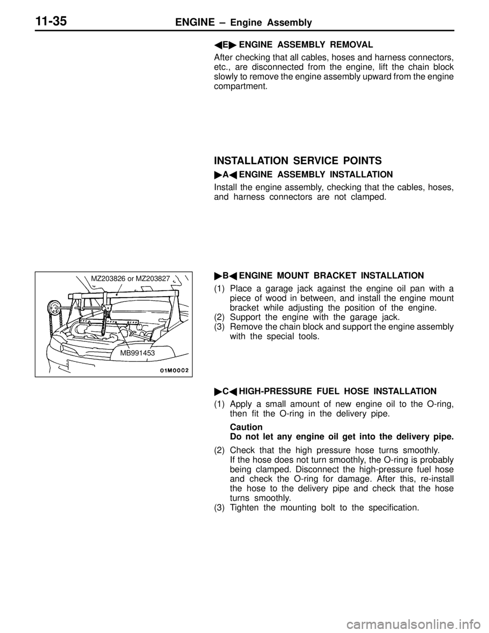
� B� ENGINE MOUNT BRACKET INSTALLATION
(1) Place a garage jack against the engine oil pan with a piece of wood in between, and install the engine mount
bracket while adjusting the position of the engine.
(2) Support the engine with the garage jack.
(3) Remove the chain block and support the engine assembly
with the special tools.
� C� HIGH-PRESSURE FUEL HOSE INSTALLATION
(1) Apply a small amount of new engine oil to the O-ring, then fit the O-ring in the delivery pipe.
Caution
Do not let any engine oil get into the delivery pipe.
(2) Check that the high pressure hose turns smoothly. If the hose does not turn smoothly, the O-ring is probably
being clamped. Disconnect the high-pressure fuel hose
and check the O-ring for damage. After this, re-install
the hose to the delivery pipe and check that the hose
turns smoothly.
(3) Tighten the mounting bolt to the specification.
MZ203826 or MZ203827
MB991453
REAR AXLE – Drive Shaft27-36
DRIVE SHAFT
REMOVAL AND INSTALLATION
Pre-removal Operation
(1) Gear Oil Draining (Refer to P.27-28.)
(2) Center Exhaust Pipe Removal
(Refer to GROUP 15.)Post-installation Operation
(1) Checking Each Ball Joint Dust Cover for Cracks
and Damages by Pressing Dust Cover with Finger
(2) Center Exhaust Pipe Installation
(Refer to GROUP 15.)
(3) Gear Oil Filling (Refer to P.27-28.)
(4) Parking Brake Lever Stroke Check and Adjustment
(Refer to GROUP 36 – On-vehicle Service.)
(5) Wheel Alignment Check and Adjustment
(Refer to GROUP 34 – On-vehicle Service.)
1
2 3
4
56 7
89 10 11
Unit: Nm {kgf�m}
25 {2.6}
74 – 87 {7.5 – 8.9}
74 – 87
{7.5 – 8.9}*88 {9.0}* 49 – 59 {5.0 – 6.0}
196 – 255 {20.0 – 26.0}
Removal steps
1. Caliper assembly
(Refer to P.27-33.)
2. Brake disc
3. Shoe & lining assembly (Refer to
GROUP 36 – Parking Brake.)
4. Clip
5. Parking brake cable connection
�A��B�6. Drive shaft nut
7. Rear speed sensor coupling
8. Trailing arm coupling
9. Lower arm coupling
10. Toe control arm coupling
�B��A�11. Drive shaftCaution
(1) With the part marked with *, first temporarily
tighten it, then ground the vehicle and tighten
it to specification in unloaded condition.
(2) When removing the drive shaft from, and
reinstalling it to, a vehicle with AYC, use care
not to damage the rotor mounted on the BJ outer
race.
 Gear Oil Draining (Refer to P.27-28.)
(2) Center Exhaust Pipe Removal
(Refer to GROUP 15.)Post-installati")