Page 7 of 396

11-1
ENGINE
CONTENTS
SERVICE SPECIFICATIONS 2. . . . . . . . . . . . . .
SEALANTS 2 . . . . . . . . . . . . . . . . . . . . . . . . . . . . . .
SPECIAL TOOLS 2 . . . . . . . . . . . . . . . . . . . . . . . .
ENGINE ADJUSTMENTS 4 . . . . . . . . . . . . . . . . .
1. Drive Belt Tension Check 4 . . . . . . . . . . . . . . .
2. Auto Tensioner Check 5 . . . . . . . . . . . . . . . . . . .
3. Lash Adjuster Check 5 . . . . . . . . . . . . . . . . . . . .
4. Lash Adjuster Replacement 7 . . . . . . . . . . . . . .
5. Ignition Timing Check 7 . . . . . . . . . . . . . . . . . . .
6. Idle Speed Check and Idle Mixture Check 7
7. Compression Pressure Check 7 . . . . . . . . . . . .
8. Manifold Vacuum Check 8 . . . . . . . . . . . . . . . . .
CRANKSHAFT PULLEY 9. . . . . . . . . . . . . . . . . .
CAMSHAFT AND CAMSHAFT
OIL SEAL 10 . . . . . . . . . . . . . . . . . . . . . . . . . . . . .
OIL PAN 13 . . . . . . . . . . . . . . . . . . . . . . . . . . . . . .
CRANKSHAFT OIL SEAL 15 . . . . . . . . . . . . . .
CYLINDER HEAD GASKET 17 . . . . . . . . . . . .
TIMING BE LT . . . . . . . . . . . . . . 21 . . . .
ENGINE ASSEMB LY 32
. . . . . . . . . . . . . . . . . . .
Page 8 of 396
ENGINE – Service Specifications / Sealants / Special Tools11-2
SERVICE SPECIFICATIONS
ItemsStandard valueLimit
Basic ignition timing5� BTDC ± 3�–
Ignition timing (at idle)Approx. 5� BTDC–
Idle speed rpm850 ± 50–
CO contents %0.6 or less–
HC contents ppm300 or less–
Compression pressure kg/cm2 – rpm11.5 – 250Min. 9.7 – 250
Compression pressure difference of all cylinders kg/cm2–Max. 1.0
Intake manifold vacuum kPa {mmHg}–Min. 55 {410}
Cylinder head bolt shank length mm–99.4
SEALANTS
ItemsSpecified sealants
Rocker coverSemi-drying sealant: THREEBOND 1207D [MZ 100168] (containing 150 g)
Oil panSemi-drying sealant: THREEBOND 1207F [MZ 100191] (containing 150 g)
NOTE:
Given in [ ] are MITSUBISHI GENUINE PART numbers.
SPECIAL TOOLS
ToolNumberNameUse
MD998782Valve lifter setReplacing the lash adjuster
MB990767End yoke holder�Holding the crankshaft pulley
�Holding the camshaft sprocket
Page 9 of 396
ENGINE – Special Tools11-3
Tool UseName Number
MD998719Crankshaft pulley
holder pin�Holding the crankshaft pulley
�Holding the camshaft sprocket
MD998715Pulley holder pin
MD998713Camshaft oil seal
installerPressfitting the camshaft oil seal
MD998727Oil pan removerRemoving the oil pan
MD998781Flywheel stopperSecuring the flywheel or drive plate
MD998776Crankshaft rear oil
seal installerPressfitting the crankshaft rear oil seal
MB990938Handle
MD998382Crankshaft front oil
seal installerInstalling the crankshaft front oil seal
MD998285Crankshaft front oil
seal guide
Page 16 of 396

ENGINE – Camshaft and Camshaft Oil Seal11-10
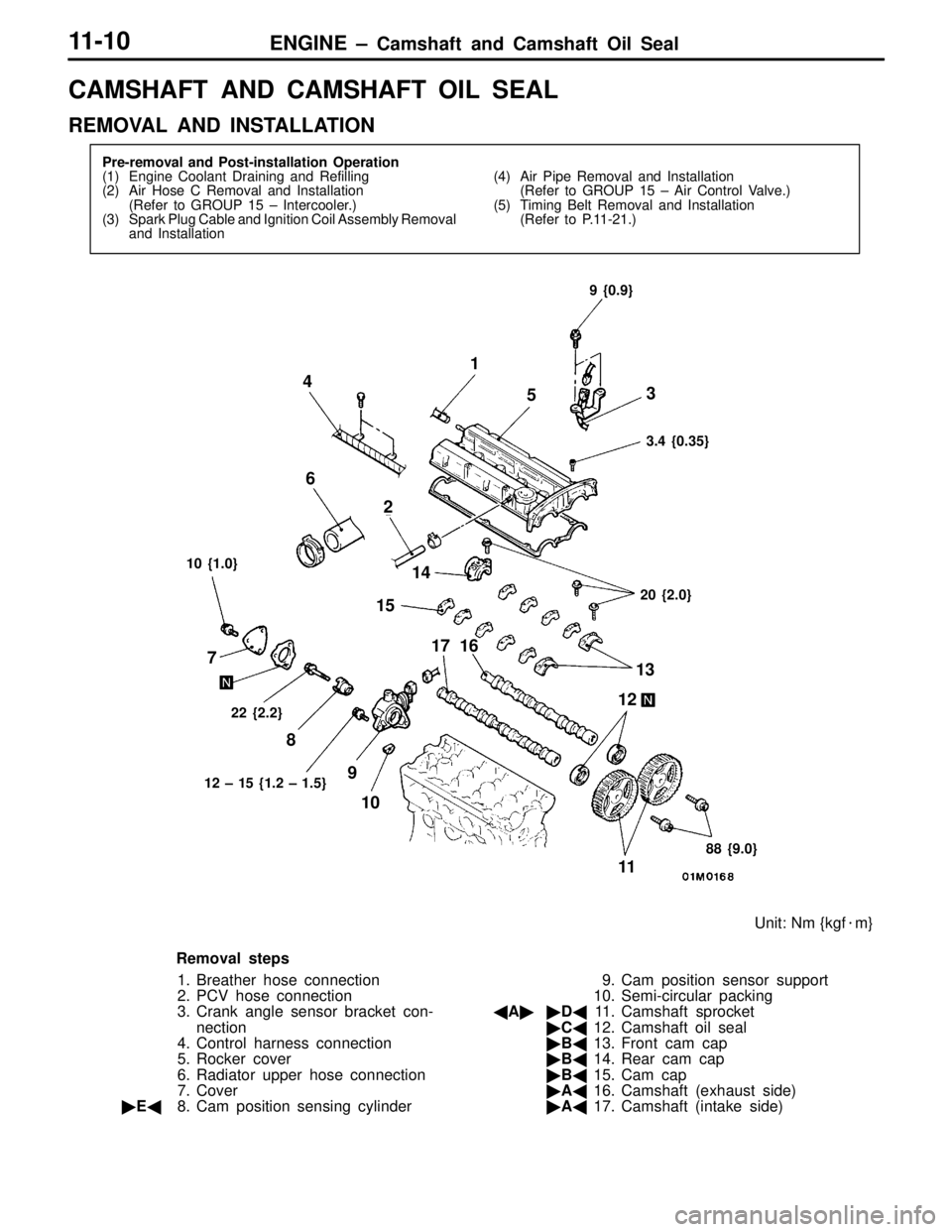
CAMSHAFT AND CAMSHAFT OIL SEAL
REMOVAL AND INSTALLATION
Pre-removal and Post-installation Operation
(1) Engine Coolant Draining and Refilling
(2) Air Hose C Removal and Installation
(Refer to GROUP 15 – Intercooler.)
(3) Spark Plug Cable and Ignition Coil Assembly Removal
and Installation(4) Air Pipe Removal and Installation
(Refer to GROUP 15 – Air Control Valve.)
(5) Timing Belt Removal and Installation
(Refer to P.11-21.)
22 {2.2}
Unit: Nm {kgf�m}
10 {1.0}9 {0.9}
3.4 {0.35}
20 {2.0}
88 {9.0} 12 – 15 {1.2 – 1.5}
1
53 4
6
2
14
15
17 16
13
12
11 10 9 8 7
Removal steps
1. Breather hose connection
2. PCV hose connection
3. Crank angle sensor bracket con-
nection
4. Control harness connection
5. Rocker cover
6. Radiator upper hose connection
7. Cover
�E�8. Cam position sensing cylinder9. Cam position sensor support
10. Semi-circular packing
�A��D�11. Camshaft sprocket
�C�12. Camshaft oil seal
�B�13. Front cam cap
�B�14. Rear cam cap
�B�15. Cam cap
�A�16. Camshaft (exhaust side)
�A�17. Camshaft (intake side)
Page 17 of 396
ENGINE – Camshaft and Camshaft Oil Seal11-11
Grease and adhesive application points
Timing belt side
Semi-drying sealant: THREEBOND 1207D
Lip 10 mm
10 mm10 mm
Semi-drying sealant:
THREEBOND 1207FEngine oil
Semi-drying sealant: THREEBOND 1207DTiming belt side
26
φ 3 mm
REMOVAL SERVICE POINT
�A�CAMSHAFT SPROCKET REMOVAL
INSTALLATION SERVICE POINTS
�A�CAMSHAFT INSTALLATION
(1) Apply engine oil to the cams and journals of the camshaft.
(2) Mount the camshaft on the cylinder head.
Caution
Make sure that the camshaft has a unique orientation
for installation, the intake side and exhaust side. The
exhaust camshaft has a slit in the rear end face.
MB990767
MD998719
Camshaft sprocket side
Camshaft (exhaust side)Slit
Page 18 of 396
ENGINE – Camshaft and Camshaft Oil Seal11-12
�B�CAM CAP / REAR CAP / FRONT CAM CAP
INSTALLATION
(1) Locate the camshaft dowel pins as illustrated.
(2) Temporarily tighten cam cap in two to three steps, then
torque it to specification.
Tightening torque: 20 Nm {2.0 kgf�m}
�C�CAMSHAFT OIL SEAL INSTALLATION
(1) Apply engine oil to the entire periphery of the oil seal
lip.
(2) Pressfit the oil seal as shown.
�D�CAMSHAFT SPROCKET INSTALLATION
As you did during removal, secure the camshaft sprocket
with the special tool and tighten bolt to specification.
Tightening torque: 88 Nm {9.0 kgf�m}
�E�CAM POSITION SENSING CYLINDER
Install the cam position sensing cylinder so that the ID paint
on the cam position sensing cylinder is 90� with respect to
the camshaft dowel pin as shown.
Intake side Approx. 12�Dowel pin
Exhaust side
MD998713
ID paintDowel pin
90�
Page 27 of 396

ENGINE – Timing Belt11-21
TIMING BELT
REMOVAL AND INSTALLATION
1
2
3
4 56
7
8
910
11 1213
14 15
16 171821
22
23
242526
27
28
20
19
11 {1.1}
11 {1.1} 11 {1.1}
88 {9.0}
49 {5.0}
9 {0.9}
48 {4.9}54 {5.5}49 {5.0} 118 {12.0}
9 {0.9}3.5 {0.35}
49 {5.0}
45 {4.6}
19 {1.9}30 {3.1} 24 {2.4}24 {2.4}
Unit: Nm {kgf�m}
Removal steps
1. Front upper cover
2. Front center cover
3. Front lower cover
4. Bracket
�A��L�5. Timing belt
�K�6. Tensioner pulley
7. Tensioner arm
�J�8. Auto tensioner
9. Idle pulley
10. Crankshaft position sensor
�B��I�11. Oil pump sprocket
�C��H�12. Crankshaft bolt
�D�13. Crankshaft sprocket
14. Sensing blade15. Tensioner B
�E��G�16. Timing belt B
�F��F�17. Counterbalance shaft sprocket
�E�18. Spacer
�G�19. Crankshaft sprocket B
20. Crankshaft key
�D�21. Rocker cover
�C�22. Semi-circular packing
�B�23. Engine support bracket
�H��A�24. Camshaft sprocket bolt
25. Camshaft sprocket
26. Timing belt rear right cover
27. Timing belt rear left upper cover
28. Timing belt rear left lower cover
Page 28 of 396

ENGINE – Timing Belt11-22
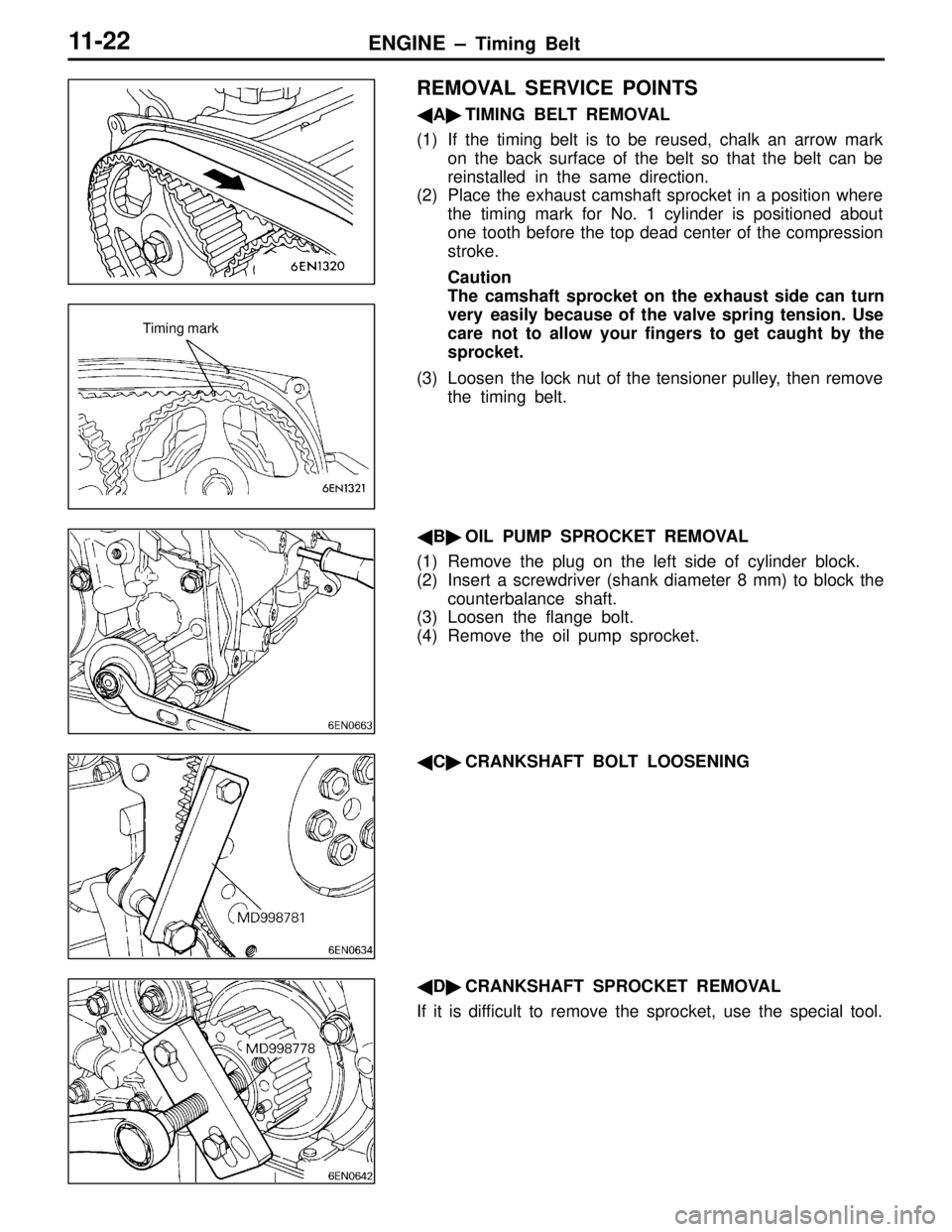
REMOVAL SERVICE POINTS
�A�TIMING BELT REMOVAL
(1) If the timing belt is to be reused, chalk an arrow mark
on the back surface of the belt so that the belt can be
reinstalled in the same direction.
(2) Place the exhaust camshaft sprocket in a position where
the timing mark for No. 1 cylinder is positioned about
one tooth before the top dead center of the compression
stroke.
Caution
The camshaft sprocket on the exhaust side can turn
very easily because of the valve spring tension. Use
care not to allow your fingers to get caught by the
sprocket.
(3) Loosen the lock nut of the tensioner pulley, then remove
the timing belt.
�B�OIL PUMP SPROCKET REMOVAL
(1) Remove the plug on the left side of cylinder block.
(2) Insert a screwdriver (shank diameter 8 mm) to block the
counterbalance shaft.
(3) Loosen the flange bolt.
(4) Remove the oil pump sprocket.
�C�CRANKSHAFT BOLT LOOSENING
�D�CRANKSHAFT SPROCKET REMOVAL
If it is difficult to remove the sprocket, use the special tool.
Timing mark