Page 29 of 396
ENGINE – Timing Belt11-23
�E�TIMING BELT “B” REMOVAL
Make an arrow mark on the back of the timing belt indicating
the direction of rotation so it may be reassembled in the
same direction if it is to be reused.
�F�COUNTERBALANCE SHAFT SPROCKET
REMOVAL
�G�CRANKSHAFT SPROCKET “B” REMOVAL
If it is difficult to remove the sprocket, use the special tool.
�H�CAMSHAFT SPROCKET BOLT LOOSENING
Use a wrench to hold the hexagonal part of the camshaft,
and then remove the camshaft sprocket mounting bolt.
INSPECTION
TIMING BELT
Replace belt if any of the following conditions exist.
(1) Hardening of back rubber.
Back side is glossy without resilience and leaves no indent
when pressed with fingernail.
6EN1322
Page 31 of 396
ENGINE – Timing Belt11-25
INSTALLATION SERVICE POINTS
�A�CAMSHAFT SPROCKET BOLT TIGHTENING
Using a wrench, hold the camshaft at its hexagon and tighten
the bolt to the specification.
Caution
Locking the camshaft sprocket with a tool damages the
sprocket.
�B�ENGINE SUPPORT BRACKET LEFT
INSTALLATION
Coat the bolts illustrated with sealant before tightening.
Specified sealant: THREEBOND 1207F or equivalent
�C�SEALANT APPLICATION ON SEMI-CIRCULAR
PACKING
Apply sealant to the areas indicated in the illustration.
Specified sealant: THREEBOND 1212D or equivalent
Apply sealant
Apply
sealant 10 mm
10 mm
Cylinder head Semi-circular
packing
Page 34 of 396

ENGINE – Timing Belt11-28
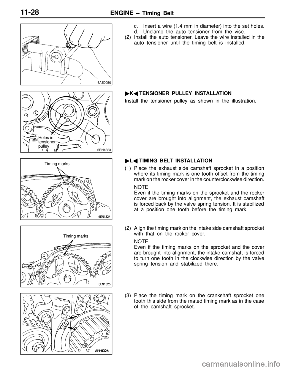
c. Insert a wire (1.4 mm in diameter) into the set holes.
d. Unclamp the auto tensioner from the vise.
(2) Install the auto tensioner. Leave the wire installed in the
auto tensioner until the timing belt is installed.
� K� TENSIONER PULLEY INSTALLATION
Install the tensioner pulley as shown in the illustration.
� L� TIMING BELT INSTALLATION
(1) Place the exhaust side camshaft sprocket in a position where its timing mark is one tooth offset from the timing
mark on the rocker cover in the counterclockwise direction.
NOTE
Even if the timing marks on the sprocket and the rocker
cover are brought into alignment, the exhaust camshaft
is forced back by the valve spring tension. It is stabilized
at a position one tooth before the timing mark.
(2) Align the timing mark on the intake side camshaft sprocket with that on the rocker cover.
NOTE
Even if the timing marks on the sprocket and the cover
are brought into alignment, the intake camshaft is forced
to turn one tooth in the clockwise direction by the valve
spring tension and stabilized there.
(3) Place the timing mark on the crankshaft sprocket one tooth this side from the mated timing mark as in the case
of the camshaft sprocket.
6AE0050
6EN1323
Holes in
tensioner
pulley
Timing marks
Timing marks
Page 35 of 396

ENGINE – T iming Belt 11-29
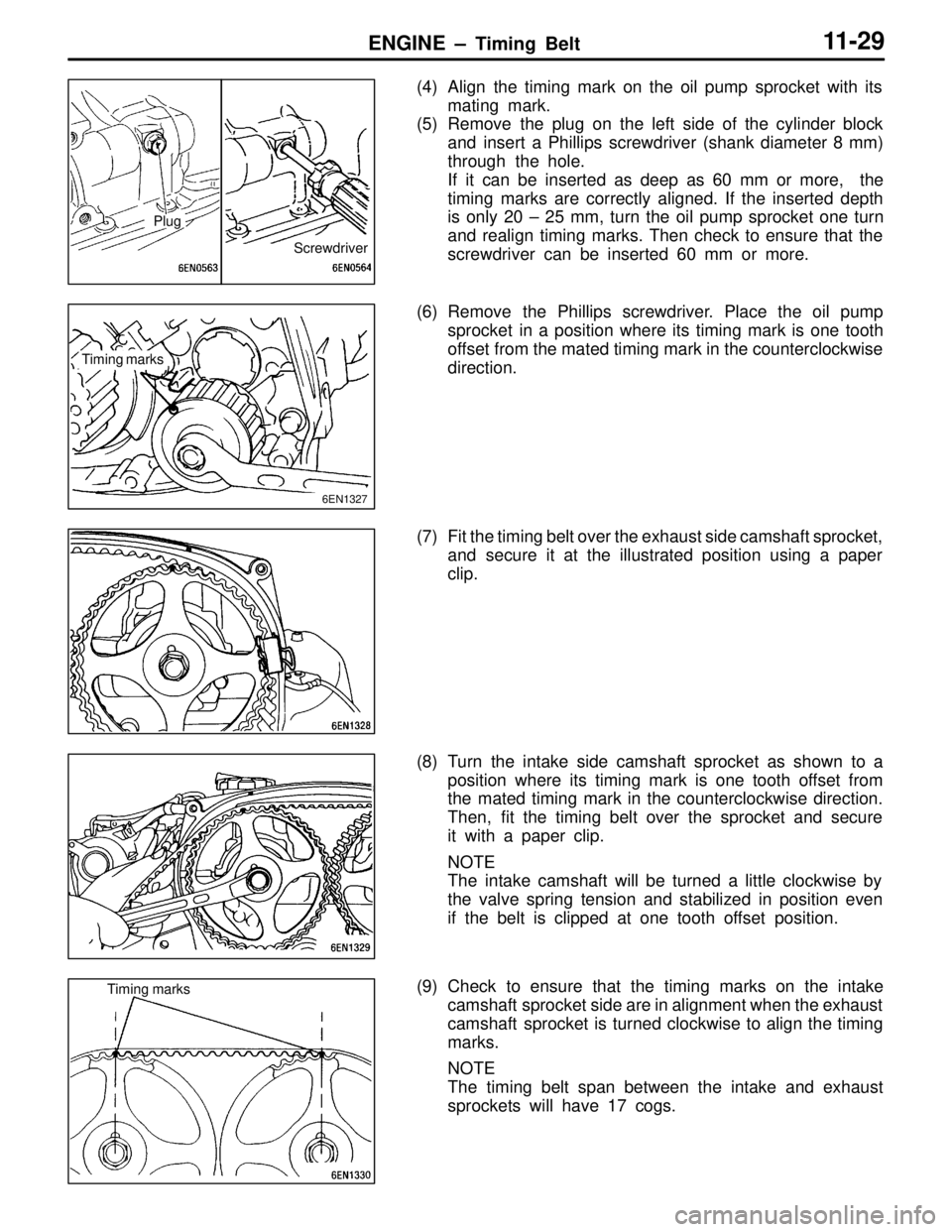
(4) Align the timing mark on the oil pump sprocket with its
mating mark.
(5) Remove the plug on the left side of the cylinder block
and insert a Phillips screwdriver (shank diameter 8 mm)
through the hole.
If it can be inserted as deep as 60 mm or more, the
timing marks are correctly aligned. If the inserted depth
is only 20 – 25 mm, turn the oil pump sprocket one turn
and realign timing marks. Then check to ensure that the
screwdriver can be inserted 60 mm or more.
(6) Remove the Phillips screwdriver. Place the oil pump sprocket in a position where its timing mark is one tooth
offset from the mated timing mark in the counterclockwise
direction.
(7) Fit the timing belt over the exhaust side camshaft sprocket, and secure it at the illustrated position using a paper
clip.
(8) Turn the intake side camshaft sprocket as shown to a position where its timing mark is one tooth offset from
the mated timing mark in the counterclockwise direction.
Then, fit the timing belt over the sprocket and secure
it with a paper clip.
NOTE
The intake camshaft will be turned a little clockwise by
the valve spring tension and stabilized in position even
if the belt is clipped at one tooth offset position.
(9) Check to ensure that the timing marks on the intake camshaft sprocket side are in alignment when the exhaust
camshaft sprocket is turned clockwise to align the timing
marks.
NOTE
The timing belt span between the intake and exhaust
sprockets will have 17 cogs.
Screwdriver
Plug
Timing marks
6EN1327
Timing marks
Page 36 of 396

ENGINE – Timing Belt11-30
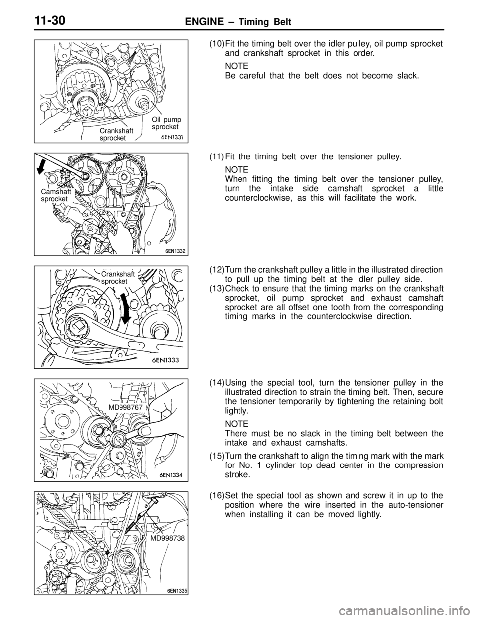
(10)Fit the timing belt over the idler pulley, oil pump sprocket
and crankshaft sprocket in this order.
NOTE
Be careful that the belt does not become slack.
(11) Fit the timing belt over the tensioner pulley. NOTE
When fitting the timing belt over the tensioner pulley,
turn the intake side camshaft sprocket a little
counterclockwise, as this will facilitate the work.
(12)Turn the crankshaft pulley a little in the illustrated direction to pull up the timing belt at the idler pulley side.
(13)Check to ensure that the timing marks on the crankshaft sprocket, oil pump sprocket and exhaust camshaft
sprocket are all offset one tooth from the corresponding
timing marks in the counterclockwise direction.
(14)Using the special tool, turn the tensioner pulley in the illustrated direction to strain the timing belt. Then, secure
the tensioner temporarily by tightening the retaining bolt
lightly.
NOTE
There must be no slack in the timing belt between the
intake and exhaust camshafts.
(15)Turn the crankshaft to align the timing mark with the mark for No. 1 cylinder top dead center in the compression
stroke.
(16)Set the special tool as shown and screw it in up to the position where the wire inserted in the auto-tensioner
when installing it can be moved lightly.
Crankshaft
sprocket Oil pump
sprocket
Camshaft
sprocket
Crankshaft
sprocket
MD998767
MD998738
Page 37 of 396

ENGINE – T iming Belt 11-31
(17)Loosen the retaining bolt of the tensioner pulley.
Caution
Loosening the retaining bolt can cause the intake
and exhaust camshafts to turn, resulting in slackened
timing belt. Use care that the timing belt does not
come off the sprockets at this time.
(18)Pull up the slack of the timing belt by turning the tensioner in illustrated direction using the special tool and a torque
wrench (0 – 5 Nm {0 – 0.5 kgf �m}).
(19)From this position, turn back the tensioner until the torque wrench reading becomes 3.5 Nm {0.36 kgf �m}, then
secure it by tightening the retaining bolt.
(20)Remove the special tool attached in step (16).
(21)Rotate the crankshaft clockwise 2 turns. Then, leave it intact 15 minutes.
(22)Check to see that the wire inserted when installing the
auto-tensioner can be pulled out lightly. If it can be pulled
out lightly, the timing belt is being tensioned properly.
If so, remove the wire. In addition, check that the rod
protrusion from the auto-tensioner meets the standard
value, which is also an indication of properly tensioned
timing belt.
Standard value: 3.8 – 4.5 mm
(23)If the wire cannot be removed with a light force, repeat steps (16) through (21) until the proper belt tensioner
is obtained.MD998767
Page 45 of 396

MPI – General Information13-2
MULTIPOINT INJECTION (MPI)
GENERAL INFORMATION
OMPI System Diagram
�1 Injector
�2 ISC servo
�3 Fuel pressure control valve
�4 Waste gate solenoid valve
�5 Secondary air control solenoid valve
�Control relay
�Fuel pump relay
�A/C relay
�Ignition coil
�Exhaust temperature warning lamp
�Engine warning lamp
�Diagnosis output
�Alternator G terminal
�Fan motor relay
�Tachometer
�Fuel pump relay No.2 �1 Oxygen sensor
�2 Air flow sensor
�3 Intake air temperature sensor
�4 Throttle position sensor
�5 Idle switch
�6 Camshaft position sensor
�7 Crank angle sensor
�8 Barometric pressure sensor
�9 High temperature sensor
�10 Engine coolant temperature sensor
�11 Detonation sensor
�Power supply voltage
�Ignition switch-IG
�Ignition switch-ST
�Vehicle speed sensor
�A/C switch
�Power steering fluid pressure switch
�Alternator FR signalEngine ECU
�1 Oxygen sensor
�2 Air flow sensor�3
Intake air tem-
perature sensor
�4,
�5
�6 Camshaft position
sensor
�7 Crank angle sensor �8 Barometric
pressure sensor
�9 High temperature
sensor �10 Coolant temperature sensor
�11 Detonation sensor�1 Injector �2 ISC servo
�3 Fuel pressure
control valve
�4 Waste gate
solenoid valve �5 Secondary air
control solenoid
valveCanister
Check valveFrom
fuel
tank
Throttle position
sensor (with a
built-in
idle
switch)
Secondary
air valve
AirTo fuel
tankFuel
pressure
regulatorFrom
fuel
pump
Waste gate
actuator
Catalytic converter
Given above is the MPI system diagram for EVOLUTION-IV. The MPI system for EVOLUTION-V is different
from this in the following point;
�Oxygen sensor with a heater is adopted.
�The diagnosis connector power supply circuit is different.
�The high temperature sensor is no longer used.
Page 49 of 396

MPI – Troubleshooting13-6
TROUBLESHOOTING
1. DIAGNOSIS FUNCTION
1-1 ENGINE WARNING LAMP (CHECK ENGINE LAMP)
If an abnormality occurs in any of the following items related
to the Multipoint Fuel Injection (MPI) system, the engine
warning lamp will illuminate.
If the lamp remains illuminated or if the lamp illuminates while
the engine is running, check the diagnosis code output.
Engine warning lamp inspection items
Engine-ECU
Air flow sensor (AFS)
Intake air temperature sensor
Throttle position sensor (TPS)
Engine coolant temperature sensor
Crank angle sensor
Camshaft position sensor
Barometric pressure sensor
Detonation sensor
Injector
Ignition coil, power transister
Misfire
1-2 METHOD OF READING AND ERASING DIAGNOSIS
CODES
(1) Use the special tool to earth No.1 terminal (diagnosis
control terminal) of the diagnosis connector.
(2) To check ABS system, remove the valve relay.
NOTE
That is because the valve relay is off and the warning
lamp remains illuminated if there is a fault in the ABS
system.
(3) Turn off the ignition switch.
(4) Read out a diagnosis code by observing how the warning
lamp flashes.
Indication of diagnosis code by warning lamp
When the diagnosis code No.24 is outputWhen no diagnosis code is output*
On
Off
1.5 secs.0.5 sec.
0.5 sec.
Pause
time 3
secs.Tens signalPlace
division
2 secs.Units signal
A03X0113
On
Off
0.5 sec.
0.25 sec.
NOTE
*: Even if the ABS system is normal, removing the valve relay causes the diagnosis code No.52 to
be output.
Engine warning lamp
(check engine lamp)