Page 1436 of 2490
Automatic Transmission/Transaxle - 4.0L SC V8 - AJ26 - Main Control
Valve Body
In-vehicle Repair
Removal
• NOTE: This procedure will not remove re sidual fluid from the torque converter.
1. Disconnect the battery ground lead.
2. Raise the vehicle for access.
3. Remove the RH catalytic converter; refer to Operation
17.50.10.
4. Remove the harness heatshield lower fixing.
Remove the screw heatshield / fluid pan clamp.
5. Remove the harness heatshield.
Pull the heatshield from under the clip.
6. Disconnect the transmission link harness connector.
1. Release the locking lever.
7. Release the (transmission case mounted) female connector.
Remove the (center) retaining bolt.
Page 1443 of 2490
Automatic Transmission/Transaxle - 4.0L SC V8 - AJ26 - Transmission
Internal Wiring Harness Electr ical Connector O-Ring Seals
In-vehicle Repair
Removal
1. Disconnect the batt ery ground cable.
2. Open the engine compartment and fit paint protection sheets.
3. Raise the vehicle for access.
4. WARNING: TRANSMISSION FLUID MAY CAUSE SEVERE
BURNS, ENSURE THAT ALL SAFET Y PROCEDURES ARE OBSERVED
AND THAT THE RECEPTACLE FOR WASTE HAS SUFFICIENT
CAPACITY.
Drain the transmission fluid.
Carefully remove the drain pl ug and discard the sealing
washer.
5. Remove the harness heatshield lower fixing.
Remove the screw heatshield / fluid pan clamp.
6. Remove the harness heatshield.
Pull the heatshield from under the clip.
7. Disconnect the transmission link harness connector.
1. Release the locking lever on the guide bush and disconnect the harness connector.
Page 1450 of 2490

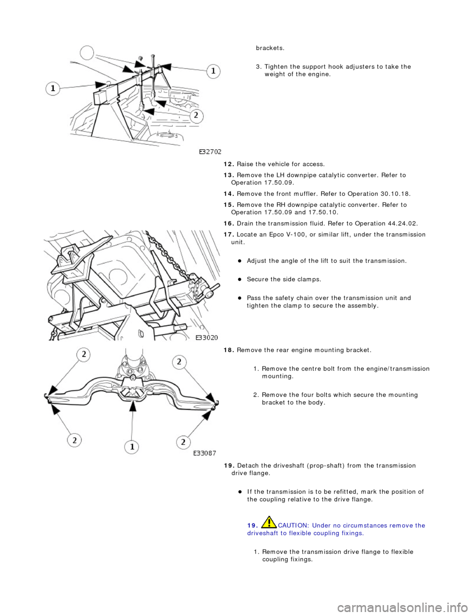
brackets.
3. Tighten the support hook adjusters to take the weight of the engine.
12. Raise the vehicle for access.
13. Remove the LH downpipe catalytic converter. Refer to
Operation 17.50.09.
14. Remove the front muffler. Re fer to Operation 30.10.18.
15. Remove the RH downpipe catalytic converter. Refer to
Operation 17.50.09 and 17.50.10.
16. Drain the transmission fluid. Refer to Operation 44.24.02.
17. Locate an Epco V-100, or sim ilar lift, under the transmission
unit.
Adjust the angle of the lift to suit the transmission.
Secure the side clamps.
Pass the safety chain over the transmission unit and
tighten the clamp to secure the assembly.
18. Remove the rear engine mounting bracket.
1. Remove the centre bolt from the engine/transmission
mounting.
2. Remove the four bolts which secure the mounting
bracket to the body.
19. Detach the driveshaft (prop- shaft) from the transmission
drive flange.
If the transmission is to be refitted, mark the position of
the coupling relative to the drive flange.
19. CAUTION: Under no circ umstances remove the
driveshaft to flexible coupling fixings.
1. Remove the transmission drive flange to flexible
coupling fixings.
Page 1454 of 2490
34. NOTE: Do not allow the converter to detach from the
transmission.
Remove the transmission / converter assembly from the
vehicle.
Lower the lift and remove the transmission, ensuring that
the torque converter spigot disengages cleanly.
35. Remove the side clamps and chain for access.
36. Remove the front muffler mounting bracket.
Remove the two bolts which secure the bracket to the
transmission case.
37. Remove the transmission dipstick tube.
1. Remove the fixing which secures the tube to the case.
Discard the filler tube 'O' ring. 2. Fit a blanking plug to the transmission casing orifice.
Page 1455 of 2490
38. Remove the harness link lead.
1. If required, slacken the harness heatshield spring
clamp bolt.
2. Remove the heatshield lower bolt.
3. Release the harness multi- lock lever, disconnect and
remove the harness.
39. If appropriate, fit retainin g straps to the converter /
transmission assembly.
Page 1522 of 2490
Exhaust System -
Torques
ComponentNm
Nut - Downpipe catalytic converter to exhaust manifold14 - 18
Bolt - Downpipe catalytic converter to lower mounting bracket39 - 51
Bolt - Front muffler mounting to gearbox (SC)22 - 28
Bolt - Front muffler mounting to front muffler cross brace (SC)22 - 28
Bolt - Over-axle mounting to rear suspension A-frame22 - 28
Torca clamps52 - 68
Oxygen sensor to downpipe40 - 50
Page 1528 of 2490
Joints and Clamps
Pipe-to-pipe joints which are slip joints, feature:
Clamping by Torca strap clamp. Indicator rings providing Maximum, Mini mum and Nominal engagement marks.
Oxygen Sensor (O2)
Location
Page 1668 of 2490

Ex
haust System - Front Muffler4.0L
NA V8 - AJ27/3.2L NA V8 - AJ26
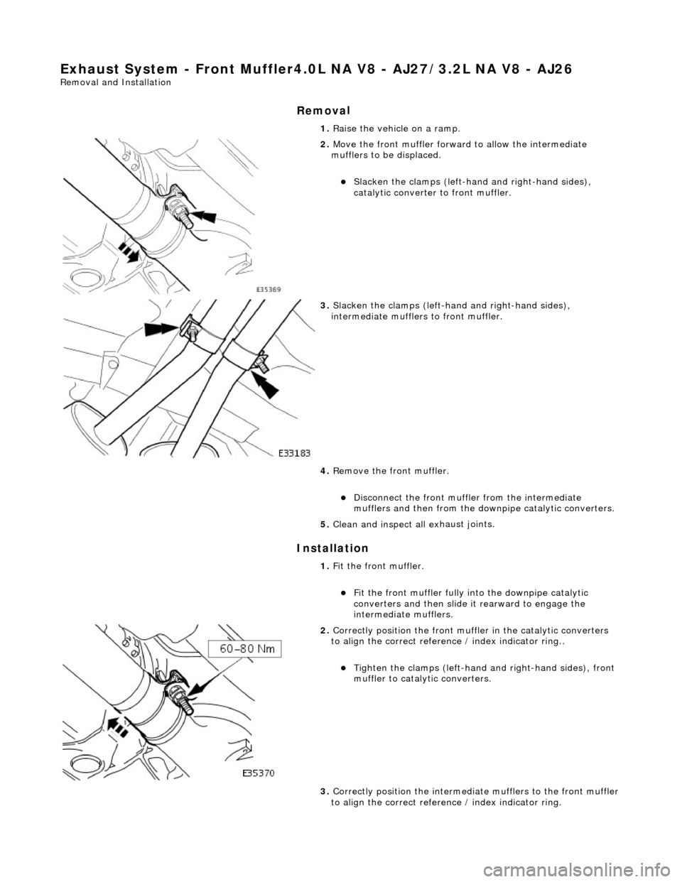
Remo
val and Installation
Remov
a
l
Installation
1. Ra
ise the vehicle on a ramp.
2. Move the front muf f
ler forwar
d to allow the intermediate
mufflers to be displaced.
Slac ken t
he clamps (left-hand and right-hand sides),
catalytic converter to front muffler.
3. Slacken the clamps (left-ha nd and right-hand sides),
i
ntermediate mufflers to front muffler.
4. Remove the front muffler.
Di
sconnect the front muffler
from the intermediate
mufflers and then from the downpipe catalytic converters.
5. Clean and inspect al l ex
haust joints.
1. Fit the front muffler.
Fi
t the front muffler fully into the downpipe catalytic
converters and then slide it rearward to engage the
intermediate mufflers.
2. Correctl
y position the front muffl
er in the catalytic converters
to align the correct reference / index indicator ring..
Tigh ten th
e clamps (left-hand
and right-hand sides), front
muffler to catalytic converters.
3. Correctly position the intermedia te mufflers to the front muffler
to align the correct refere nce / index indicator ring.