Page 930 of 2490

Whe r
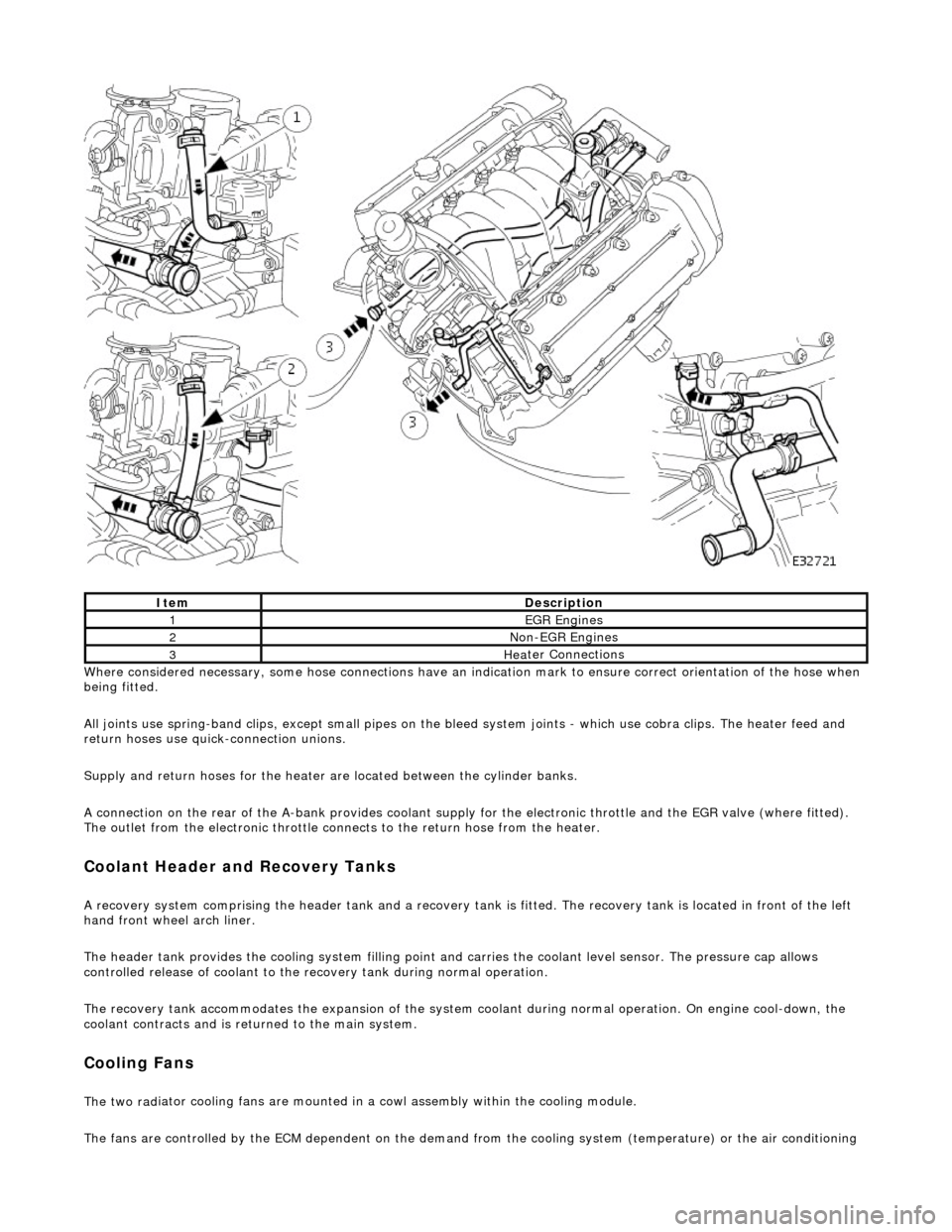
e considered necessary, some hose conn
ections have an indication mark to ensure correct orientation of the hose when
being fitted.
All joints use spring-band clips, except small pipes on the bleed system joints - which use cobra clips. The heater feed and
return hoses use quick-connection unions.
Supply and return hoses for the heater are located between the cylinder banks.
A connection on the rear of the A-bank provides coolant supply for the electronic throttle and the EGR valve (where fitted).
The outlet from the electronic throttle connects to the return hose from the heater.
Cool
ant Header and Recovery Tanks
A recovery system comp
rising the header tank
and a recovery tank is fitted. The recove ry tank is located in front of the left
hand front wheel arch liner.
The header tank provides the cooling system filling point and carries the coolant level sensor. The pressure cap allows
controlled release of coolant to the re covery tank during normal operation.
The recovery tank accommodates the expansion of the system coolant during normal operation. On engine cool-down, the
coolant contracts and is returned to the main system.
Coo lin
g Fans
The two
rad
iator cooling fans are mounted in
a cowl assembly within the cooling module.
The fans are controlled by the ECM dependent on the demand fr om the cooling system (temperature) or the air conditioning
ItemDescrip
tion
1EGR
E
ngines
2Non
-
EGR Engines
3Hea
ter Connections
Page 953 of 2490
Engine Cooling - Cooling System Draining,
Filling and Bleeding4.0L NA V8
- AJ27/3.2L NA V8 - AJ26
Gen
eral Procedures
Drain
Refill
1. O
pen the engine compartment and fit paintwork protection
sheets.
2. Ensure that the cooling system is cool and very carefully,
remove the pressure cap from the header tank.
3. Raise the vehicle.
4. Drain th
e coolant.
Pla
ce a coolant drain tray on
the floor, below the radiator
drain plug.
1. Remove the radiator drain plug. and allow the coolant to drain.
5. Fit a new seal to the
drain plug.
1. Remove the seal from the drain plug. and clean the plug face.
Fit a new seal.
6. Re
fit the radiator drain plug.
Cl
ean any coolant from the
underside of the vehicle.
Remove the drain tray.
7. Lower the vehicle.
1. Refill the cooling system with a 50% solution of water and
Jaguar Antifreeze / Corrosion Inhibitor ESD-M97B49-A.
1. Fill the cooling system at the header tank until the level stabilises at the top of the breather neck.
Page 955 of 2490
Engine Cooling - Cooling System Draining, Filling and Bleeding4.0L SC V8 -
AJ26
Gen
eral Procedures
Drain
Refill
1. O
pen the engine compartment and fit paintwork protection
sheets.
2. Ensure that the cooling system is cool and very carefully,
remove the pressure cap from the header tank.
3. Raise the vehicle.
4. Drain th
e coolant.
Pla
ce a coolant drain tray on
the floor, below the radiator
drain plug.
1. Remove the radiator drain plug. and allow the coolant to drain.
5. Fit a new seal to the
drain plug.
1. Remove the seal from the drain plug. and clean the plug face.
Fit a new seal.
6. Re
fit the radiator drain plug.
Cl
ean any coolant from the
underside of the vehicle.
Remove the drain tray.
7. Lower the vehicle.
1. Refill the cooling system with a 50% solution of water and
Jaguar Antifreeze / Corrosion Inhibitor ESD-M97B49-A.
1. Remove the threaded plug and Dowty washer from the charge air cooler fill point.
Page 1001 of 2490

Engine Cooling - Water Pump4.0L NA V8 - AJ27/ 3.2L NA V8 - AJ26
Re
moval and Installation
Remov
al
1.
O
pen the engine compartment and fit paintwork protection
sheets.
2. Drain the cooling system.
For additional information, refer to Cooling System Draining,
Fillin
g and Bleeding
- Vehicles W
ithout: Supercharger
in
this
section.
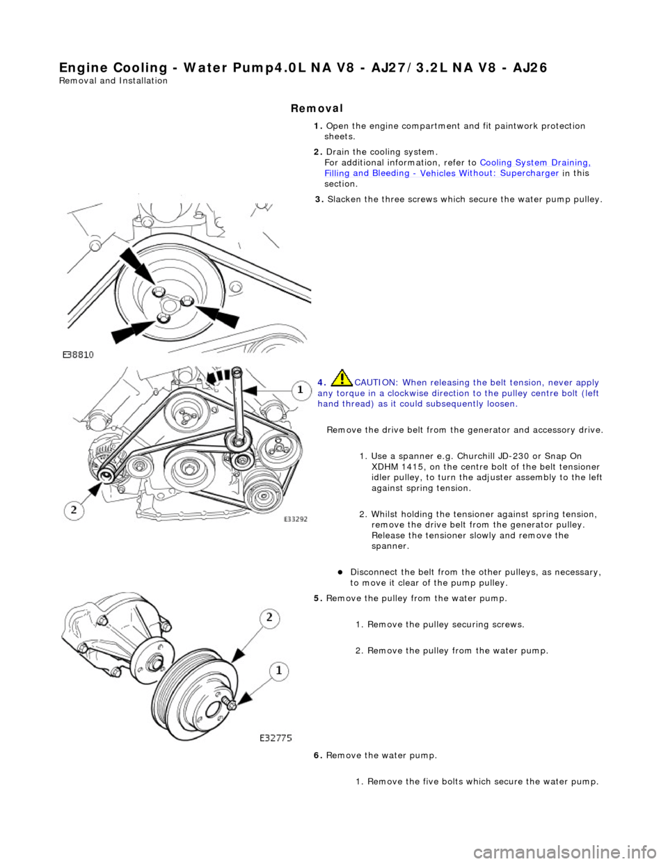
3. Sl
acken the three screws which
secure the water pump pulley.
4. CAUTI
ON: When releasing the
belt tension, never apply
any torque in a clockwise direction to the pulley ce ntre bolt (left
hand thread) as it could subsequently loosen.
Remove the drive belt from the generator and accessory drive.
1. Use a spanner e.g. Churchill JD-230 or Snap On XDHM 1415, on the centre bo lt of the belt tensioner
idler pulley, to turn the adju ster assembly to the left
against spring tension.
2. Whilst holding the tensioner against spring tension, remove the drive belt from the generator pulley.
Release the tensioner sl owly and remove the
spanner.
D
isconnect the belt from the ot
her pulleys, as necessary,
to move it clear of the pump pulley.
5. Re
move the pulley from the water pump.
1. Remove the pulley securing screws.
2. Remove the pulley from the water pump.
6. Remove the water pump.
1. Remove the five bolts wh ich secure the water pump.
Page 1003 of 2490
4.
Fi
ll the cooling system.
For additional information, refer to Cooling System Draining,
Fillin
g and Bleeding
- Vehicles W
ithout: Supercharger
in
this
section.
Page 1004 of 2490

Engine Cooling - Water Pump4.0L SC V8 - AJ26
Remo
val and Installation
Remov
a
l
1.
Op
en the engine compartment and fit paintwork protection
sheets.
2. Drain the cooling system.
For additional information, refer to Cooling System Draining,
Filling and Bleedin
g
- Vehicles With
: Supercharger in this
section.
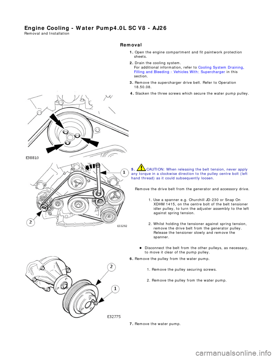
3. Remove the supercharger driv e belt. Refer to Operation
18.50.08.
4. Slacken the three screws whi
ch
secure the water pump pulley.
5. CAUTIO
N: When releasing the
belt tension, never apply
any torque in a clockwise direction to the pulley ce ntre bolt (left
hand thread) as it could subsequently loosen.
Remove the drive belt from the generator and accessory drive.
1. Use a spanner e.g. Churchill JD-230 or Snap On XDHM 1415, on the centre bo lt of the belt tensioner
idler pulley, to turn the adju ster assembly to the left
against spring tension.
2. Whilst holding the tensioner against spring tension, remove the drive belt from the generator pulley.
Release the tensioner sl owly and remove the
spanner.
Di
sconnect the belt from the ot
her pulleys, as necessary,
to move it clear of the pump pulley.
6. Remove t
he pulley from the water pump.
1. Remove the pulley securing screws.
2. Remove the pulley from the water pump.
7. Remove the water pump.
Page 1006 of 2490
4.
Fill
the cooling system.
For additional information, refer to Cooling System Draining,
Filling and Bleedin
g
- Vehicles With
: Supercharger in this
section.
Page 1071 of 2490
I
nstallation
8.
The u
pper bolt may be removed (a
fter loosening) using a 3/8"
square drive 13 mm socket, ex tensions and U.J as shown.
1. Installation is the reverse of the removal procedure. Tighten
the starter motor securing bolts to 38-48 Nm.
2. Refit the steering rack as detail ed in Operation 57.10.01. Refill
the reservoir with the reco mmended fluid and bleed the
steering system.
3. Lower the ramp. Remove the protection sheets and close the
engine compartment cover.
4. Connect the battery and fit the battery cover.
R
eset the radio informat
ion and the clock.
Page 2
of 2