Page 1099 of 2490
6. R
emove the EGR valve to throttle
body elbow retaining bolts.
Remove an
d discard the EGR valve to throttle body elbow
gasket.
7. R
emove the exhaust manifold to EGR valve tube retaining
bolts.
Remove an
d discard the exhaust manifold to EGR valve
tube gasket.
8. N
OTE: Note the orientation of the coolant hose to EGR valve
before removal.
Remove the coolant hose.
9. NOTE: Note the orientation of the coolant hose to EGR valve
before removal.
• NOTE: Cap the coolant hose to minimize coolant loss.
Remove the EGR valve.
Page 1100 of 2490
In
stallation
1.
NO TE
: Make sure the EGR valve to the coolant hose is installed
to the orientation noted during removal.
• NOTE: Un-cap the coolant hose.
Install the EGR valve.
2. NO TE
: Make sure the EGR valve to the coolant hose is installed
to the orientation noted during removal.
Install the coolant hose.
3. NOTE:
Install a new exhaust manifold to EGR valve tube
gasket.
• NOTE: Install a new EGR valve to throttle body elbow gasket.
Loosely install the exhaust manifold to EGR valve tube and the
EGR valve to throttle body elbow.
4. Tighten the exhaust manifold to EGR valve tube retaining
bolts.
Tigh te
n to 21 Nm.
Page 1101 of 2490
5. Tigh
ten the EGR valve to throttle body retaining bolts.
Tigh
ten to 12 Nm.
6. Con
nect the EGR valve electrical connector.
7. NO
TE: Un-cap the coolant hose.
Connect the coolant hose.
8. Attach the evaporative emission canister purge valve.
Tigh
ten to 6 Nm.
Page 1103 of 2490
E
ngine Emission Control - Exhaust Ma
nifold to Exhaust Gas Recirculation
(EGR) Valve Tube
Re
moval and Installation
Remov
al
1.
R
emove the engine cover.
For additional informat ion, refer to Section 501
-0
5 Interior
Trim and Ornamen
tation
.
2. Di
sconnect the evaporative emission canister purge valve
electrical connector.
3. De
tach and reposition the evaporative emission canister purge
valve.
4. Di
sconnect the exhaust gas recirc
ulation (EGR) valve electrical
connector.
5. Remove the exhaust manifold to EGR valve tube retaining
bolts.
Remove an
d discard the exhaust manifold to EGR valve
tube gasket.
Page 1104 of 2490
In
stallation
6.
Re
move the exhaust manifold to EGR valve tube.
Remove and discard the ex
haust manifold to EGR valve
tube gasket.
1. NOTE:
Install a new exhaust manifold to EGR valve tube
gasket.
Loosely install the exhaust manifold to EGR valve tube.
2. NOTE:
Install a new exhaust manifold to EGR valve tube
gasket.
Install the exhaust manifold to EGR valve tube retaining bolts.
Tigh te
n to 21 Nm.
3. Tighten the exhaust manifold to EGR valve tube retaining bolts.
Tighte
n to 21 Nm.
Page 1111 of 2490

the
intake elbow provide connections for vacuum actuators and are also used to redirect emissions into the engine.
On the right-hand side of the elbow a la rge diameter pipe connects to the brake servo. The smaller pipe provides a vacuum
feed to the fuel rail pressure regulator and throttle cruise control system. On the le ft-hand side of the elbow the front pipe
supplies vacuum control for the evaporative emissions system valves.
Emissions from the engine part load breather (bank 2) and pu rged fuel vapor from the EVAP valve are drawn via a common
T piece into the left-hand side of the intake elbow. Re-cir culated exhaust gas enters the intake elbow via the EGR valve
which is mounted directly on the rear of the elbow : where the EGR system is not used, a blanking plate is fitted.
The fuel system, throttle and emission control system s are described more fully in the relevant sections.
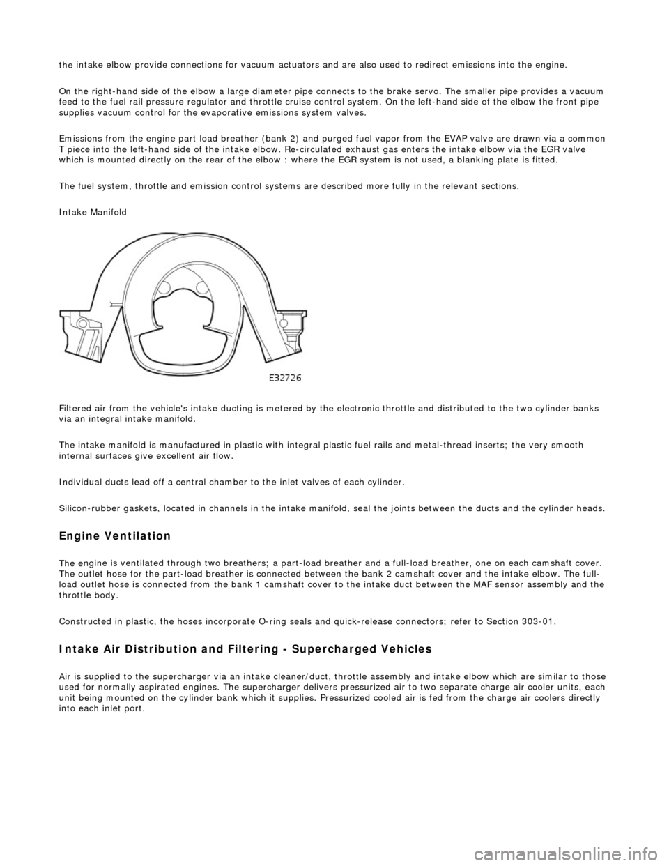
Intake Manifold
Filtered air from the vehicle's intake ducting is metered by th e electronic throttle and distributed to the two cylinder banks
via an integral intake manifold.
The intake manifold is manufactured in plastic with integral plastic fuel rails and metal-thread inserts; the very smooth
internal surfaces give excellent air flow.
Individual ducts lead off a central chamber to the inlet valves of each cylinder.
Silicon-rubber gaskets, loca ted in channels in the intake manifold, seal th e joints between the ducts and the cylinder heads.
Engine Ventilation
The e
ngine is ventilated through two brea
thers; a part-load breather and a full-load breather, one on each camshaft cover.
The outlet hose for the part-load breather is connected between the bank 2 camshaft cover and the intake elbow. The full-
load outlet hose is connected from the bank 1 camshaft cover to the intake duct between the MAF sensor assembly and the
throttle body.
Constructed in plastic, the hoses incorporate O-ring seal s and quick-release connectors; refer to Section 303-01.
I
ntake Air Distribution and Filtering - Supercharged Vehicles
Ai
r is supplied to the supercharger via an
intake cleaner/duct, throttle assembly and intake elbow which are similar to those
used for normally aspirated engines. The su percharger delivers pressurized air to two separate charge air cooler units, each
unit being mounted on the cy linder bank which it supplies. Pr essurized cooled air is fed from the charge air coolers directly
into each inlet port.
Page 1113 of 2490

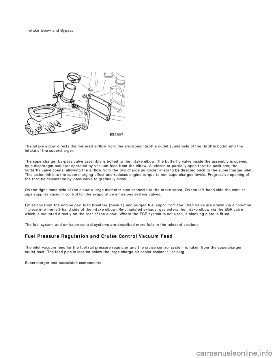
The intake elbow di
rects the metered airflow from the electronic throttle outlet (und
erside of the throttle body) into the
intake of the supercharger.
The supercharger by-pass valve assembly is bolted to the intake elbow. The butterfly valve inside the assembly is opened
by a diaphragm actuator operated by vacu um feed from the elbow. At closed or partially open throttle positions, the
butterfly valve opens, allowing th e airflow from the two charge air cooler inlets to be directed back to the supercharger inlet .
This action inhibits the supercharging e ffect and reduces engine torque to non supercharged levels. Progressive opening of
the throttle causes the by-pass valve to gradually close.
On the right-hand side of the elbow a la rge diameter pipe connects to the brake servo. On the left-hand side the smaller
pipe supplies vacuum control for the evaporative emissions system valves.
Emissions from the engine part load breather (bank 1) and pu rged fuel vapor from the EVAP valve are drawn via a common
T piece into the left-hand side of the intake elbow. Re-cir culated exhaust gas enters the intake elbow via the EGR valve
which is mounted directly on the rear of the elbow. Where the EGR system is not used, a blanking plate is fitted.
The fuel system and emission control systems are described more fully in the relevant sections.
Fuel Pressure Regula
tion and
Cruise Control Vacuum Feed
The inlet v
acuum feed fo
r the fuel rail pressure regula tor and the cruise control system is taken from the supercharger
outlet duct. The feed pipe is located below the large charge air cooler coolant filler plug.
Superchar
ger
and associated components
Inta
ke Elbow and Bypass
Page 1120 of 2490

Intake Air Distribution and Filtering - Charge Air Cooler LH
Remo
val and Installation
Remov
a
l
Installation
1. Disc onne
ct battery ground cable (IMPORTANT, see SRO
86.15.19 for further information).
2. Drain radiator coolant; refer to 26.10.01.
3. Remove air cleaner cover / intake assembly; refer to 19.10.30.
4. Remove throttle body; refer to 19.70.04.
5. Remove exhaust gas re-circulation valve (EGR) if installed;
refer to 17.45.01.
6. Remove throttle intake elbo w; refer to (SC) 19.70.28.
7. Remove supercharger outlet duct; refer to 18.50.16.
8. Remove coolant outlet pipe; refe r to operation (SC) 26.31.08.
9. Remove supercharger drive belt; refer to 18.50.08.
10. Remove supercharger; refer to operation 18.50.15.
11. Detach engine harness retaining clip from rear of charge air
cooler.
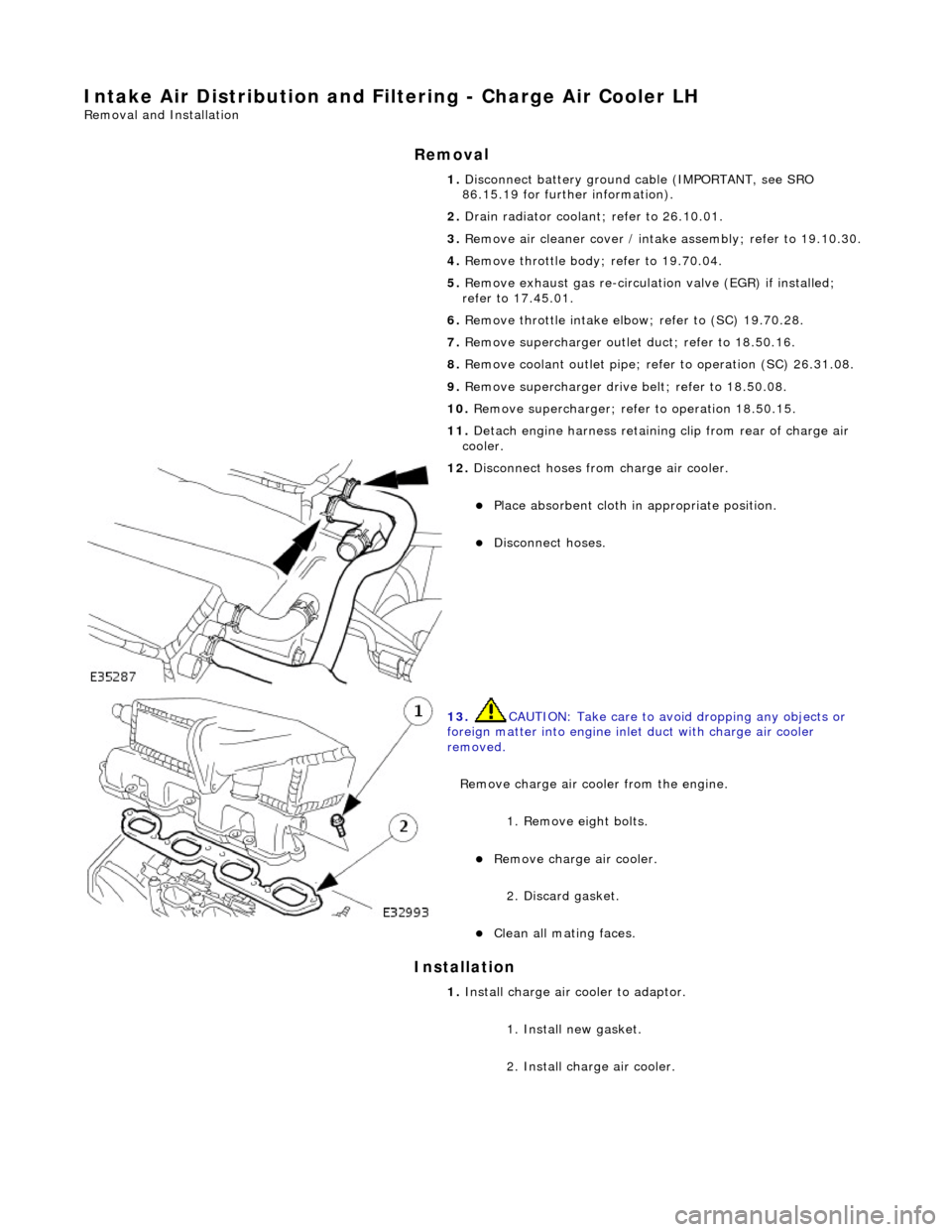
12. Di
sconnect hoses from charge air cooler.
Pla
ce absorbent cloth in appropriate position.
Di
sc
onnect hoses.
13 .
CAUTI
ON: Take care to avoi
d dropping any objects or
foreign matter into engine inle t duct with charge air cooler
removed.
Remove charge air cooler from the engine.
1. Remove eight bolts.
Remove charge air cooler.
2
. Discard gasket.
Cle
a
n all mating faces.
1.
Install ch
arge air
cooler to adaptor.
1. Install new gasket.
2. Install charge air cooler.