Page 2402 of 2490
FOAM INJECTION
Where any of the sections shown in the illustration are renewed, expanded foam must be introduced into the area on
completion of all other repair / refinishin g / protective processes. Tape should be applied to the areas indicated by arrows to ensure full travel of foam along the holl ow sections.Expanded foam should be introd uced at the points circled. Items such as sliding roof drain tubes and the harness from the rear left-hand bulkhead through to the luggage compartment, must be in
position before the introduction of foam.
Foam Injection Points
Page 2405 of 2490

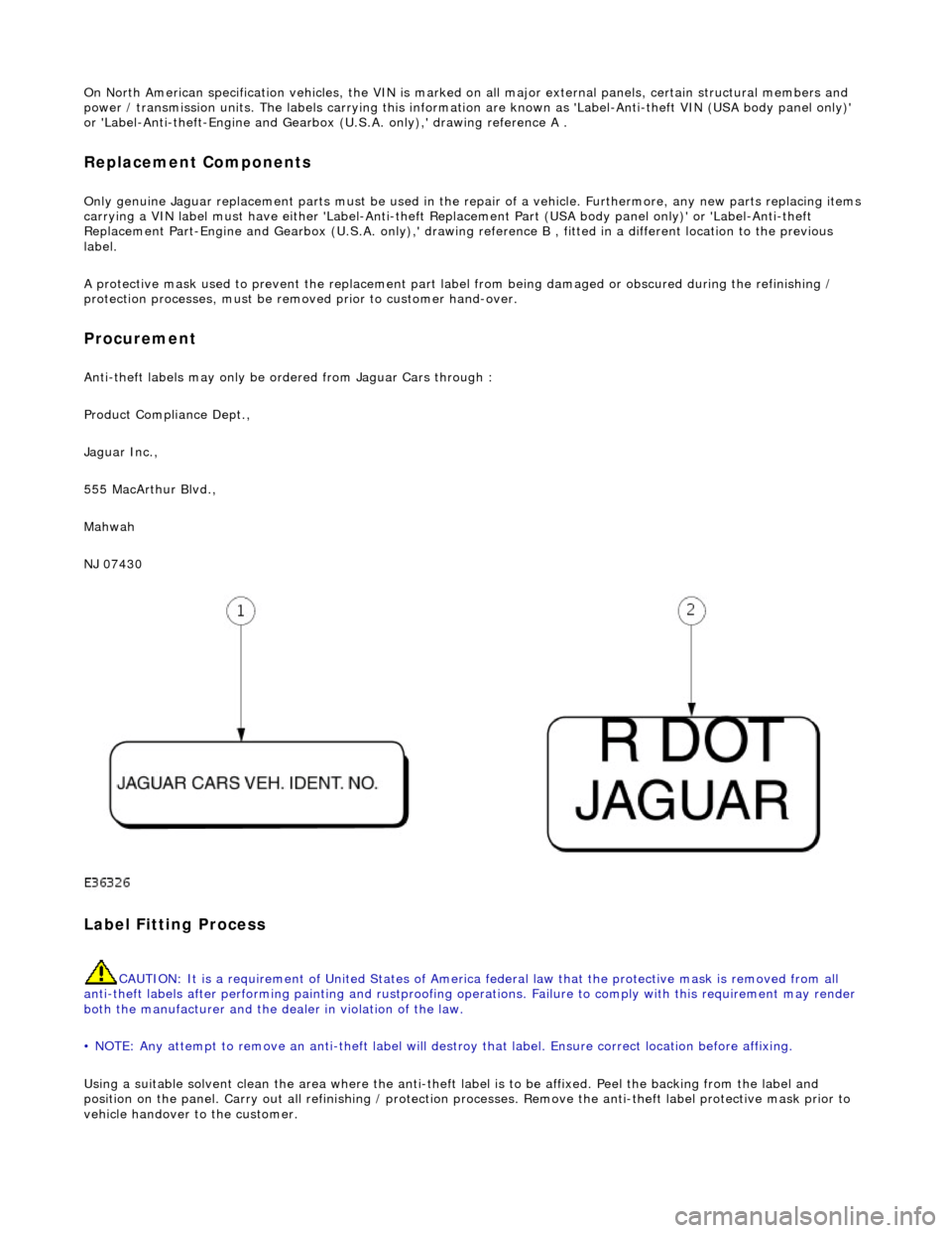
On North American specification vehicles, the VIN is marked on all major external panels, certain structural members and
power / transmission units. The labels ca rrying this information are known as 'Label-Anti-theft VIN (USA body panel only)'
or 'Label-Anti-theft-Engine and Gearbo x (U.S.A. only),' drawing reference A .
Replacement Components
Only genuine Jaguar replacement parts must be used in the repair of a vehicle. Furthermore, any new parts replacing items
carrying a VIN label must have either 'Label-Anti-theft Replacement Part (USA body panel only)' or 'Label-Anti-theft
Replacement Part-Engine and Gearbox (U.S.A . only),' drawing reference B , fitted in a different location to the previous
label.
A protective mask used to prevent the replacement part la bel from being damaged or obscured during the refinishing /
protection processes, must be remo ved prior to customer hand-over.
Procurement
Anti-theft labels may only be ordered from Jaguar Cars through :
Product Compliance Dept.,
Jaguar Inc.,
555 MacArthur Blvd.,
Mahwah
NJ 07430
Label Fitting Process
CAUTION: It is a requirement of United States of America federal law th at the protective mask is removed from all
anti-theft labels after performing painting and rustproofing operations. Fail ure to comply with this requirement may render
both the manufacturer and the de aler in violation of the law.
• NOTE: Any attempt to remove an anti-t heft label will destroy that label. Ensure correct location before affixing.
Using a suitable solvent clean the area where the anti-theft label is to be affixed. Peel the backing from the label and
position on the panel. Carry out all refini shing / protection processes. Remove the anti-theft label protective mask prior to
vehicle handover to the customer.
Page 2417 of 2490

Panels centered between two adjacent panels must have equal gaps on either side. For exceptions to this, refer to the
appropriate specification. Gaps between ad jacent panels or components must not expose harnesses, labels, brackets or
visually poor joint or assembly conditions.
• NOTE: Sliding roof panel clearances are specified without the edge seal installed.
Areas of particular concern are, fuel filler flap, trunk lid to fenders and saddle panels, hood to fenders, grill and headlamps,
sliding roof to main roof panel, door gaps at fenders, B\C posts, roof drip rail an d rocker panel, and bumper cover to fenders
and cross car assemblies
Alignment
Panels must be correctly profiled to maintain cosmetic appearance, and ensure co rrect seating of seals with minimal wind
noise. Areas of particular concern are hood to fenders, trunk lid to fenders and saddle panels, doors to apertures, doors to
fenders and adjacent doors and relationship of the sliding roof panel leading and trailing edges to the main roof panel.
Exterior Fitments
Bezels, trims and lamps must be concentric with apertu res and have equal clearances with adjacent panels.
Areas of particular concern are headlamp to hood, fender and trim panel, exhaust tailpipe trim to bumper cover cut-out,
rear lamp assembly to trunk lid, fender and bumper cover trim, and side feature lines including body side mouldings, fender
to door and door to door.
Exterior Clearances and Alignments-Front
Page 2419 of 2490
Sliding Roof
Description
Sliding roof operating features include a tilt facility, one touch slide opening and closing, intermediate slide position closing
(this also operates from tilt openings of less than 4mm), and a wind deflector. The sliding roof is operated by a cable and
Page 2420 of 2490

lever mechanism driven by an electric motor. A sliding roof control module (SRCM) controls the motor in response to
selections made on the roof console switch , or input from the security system for automatic closing. Both the motor and the SRCM are accessed by removing the roof console.In the event of an electrical failure the sliding roof can be manually
operated. This is achieved by inserting a wide bladed screwdriver into a slot in the motor drive gear and turning clockwise to open or counter clockwise to close the sliding roof.
• NOTE: The drive gear becomes disengaged from the motor during manual operation. Before restoring electrical operation
the drive gear must be rotated one quarter turn in the reverse direction to re-engage the motor.
The SRCM is held in position by clips and has two electrical connectors in terfacing with the motor and the roof console
switch/security system. Prior to installing a new SRCM, the sun ro of must be in a neutral closed position. This provides the
SRCM with a sliding roof datum, to ensure accurate and consistent operation. Obstacle sensin g operates on closing in the
slide mode only. If the sliding roof lid encounters an ob struction between 4mm and 200mm from the closed position, the
SRCM detects increased motor load and reve rses the motor, driving the sliding roof to the fully open position. The sliding
roof lid surround seal has a metal inner sect ion which will deform on removal. If removed, this seal must be discarded and a
new seal must be installed on the lid using a Jaguar approved crimping tool.