Page 2120 of 2490
4. Press mounting block onto marked area and hold in position for one minute.
5. After a period of 15 minutes, remove and discard masking
tape.
6. Using a scraper, carefully re move any excess adhesive.
7. NOTE: The following time is the MINIMUM PERIOD required for
adhesive curing. Failure to allow th is period will result in bonding
failure, necessitating repeat of the complete procedure.
After a further period of at le ast 6 hours, install mirror on
mounting block. Refer to 76.10.51 or 76.10.56.
8. Install roof console. Refer to 76.13.69.90.
9. Install rain sensor unit. Refer to Section 501.16.
10. Remove protective cover from facia.
11. Connect ground cable to batter y terminal and install battery
cover. Refer to 86.15.15.
Page 2197 of 2490
15. Adjust regulator up stop.
Slacken stop securing bolt.
Move stop rearwards to abut regulator quadrant.
Tighten stop securing bolt an d apply waterproof tape to
aperture in water shedder.
16. Reconnect harness multiplug to lift motor.
17. Fit door module. Refer to 86.80.34.
18. Reposition PVC weathershield.
19. Position water shedder and carefully pass harness multiplugs
through penetration.
20. Ensuring door mating surfaces ar e clean and dry, firmly seat
water shedder.
21. Fit casing/armrest assembly to door. Refer to 76.34.01.
22. Connect ground cable to batter y terminal and fit cover to
battery. Refer to 86.15.15.
Page 2203 of 2490

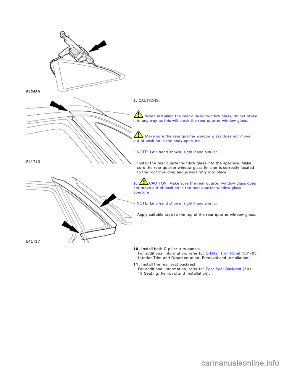
8. CAUTIONS:
When installing the rear quarte r window glass, do not strike it in any way as this will crack the rear quarter window glass.
Make sure the rear quarter window glass does not move
out of position in the body aperture.
• NOTE: Left-hand shown, right-hand similar.
Install the rear quar ter window glass into the aperture. Make
sure the rear quarter window glas s finisher is correctly located
to the roof moulding and press firmly into place.
9. CAUTION: Make sure the rear quarter window glass does
not move out of position in the rear quarter window glass
aperture.
• NOTE: Left-hand shown, right-hand similar.
Apply suitable tape to the top of the rear quarter window glass.
10. Install both C-pillar trim panels.
For additional information, refer to: C-Pillar Trim Panel (501-05
Interior Trim and Ornamentatio n, Removal and Installation).
11. Install the rear seat backrest.
For additional information, refer to: Rear Seat Backrest
(501-
10 Seating, Removal and Installation).
Page 2267 of 2490
Instrument Panel and Console - Overhead Console
Removal and Installation
Removal
1. Remove battery cover and disconnect ground cable from
battery terminal. Refer to 86.15.19.
2. Open roof console sun glasses compartment.
3. Rotate fastener 1/4 turn to release console.
4. Lower console from roof and disconnect lighting module
harness multiplug and hands- free microphone harness
multiplug if telephone is fitted.
5. Release roof console from retaining clips and remove from
vehicle.
Page 2268 of 2490
Installation
1.
Position roof console at headlini ng and connect lighting harness
multiplug and hands-free microphone multiplug if fitted.
2. Engage console in retaining clips.
3. Aligning with headlining aperture, seat console and rotate
fastener 1/4 turn to secure.
4. Close sunglasses compartment.
5. Connect ground cable to battery terminal and fit battery cover.
Refer to 86.15.15.
Page 2306 of 2490

Wipers and Washers - Wipers and Washers
Description and Operation
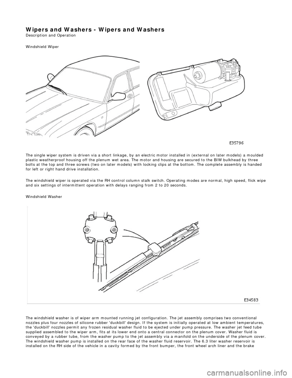
Windshield Wiper
The single wiper system is driven via a sh ort linkage, by an electric motor installed in (external on later models) a moulded
plastic weatherproof housing o ff the plenum wet area. The motor and housing are secured to the BIW bulkhead by three
bolts at the top and three screws (two on later models) with locking clips at the bottom. The complete assembly is handed
for left or right hand drive installation.
The windshield wiper is operated via the RH control column stalk switch. Operating modes are normal, high speed, flick wipe
and six settings of intermittent operation with delays ranging from 2 to 20 seconds.
Windshield Washer
The windshield washer is of wiper arm mounted running jet configuration. The je t assembly comprises two conventional
nozzles plus four nozzles of silicone rubbe r 'duckbill' design. If the system is initially operated at low ambient temperatures ,
the 'duckbill' nozzles permit an y frozen residual washer fluid to be ejected un der pump pressure. The washer jet feed tube
supplied assembled to the wiper ar m, fits at its lower end onto a central connector on the pl enum cover. Washer fluid is
conveyed by a rubber tube, from the washer pump to the jet assembly via a manifold on the underside of the plenum cover.
The windshield washer pump is installed on the rear face of the washer fluid reservoir. The 6.3 liter washer reservoir is
installed on the RH side of th e vehicle in a cavity formed by the front bu mper, the front wheel arch liner and the brake
Page 2328 of 2490

Roof Opening Panel - Roof Opening Panel
Description and Operation
General Description
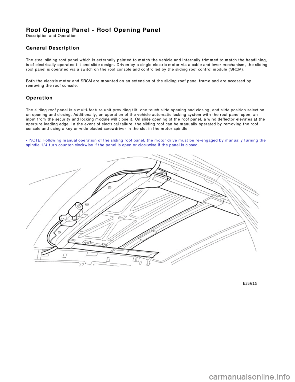
The steel sliding roof panel which is externally painted to ma tch the vehicle and internally trimmed to match the headlining,
is of electrically operated tilt and slide design. Driven by a single electric motor via a cable and lever mechanism, the slidi ng
roof panel is operated via a switch on the roof console and controlled by the sliding roof control module (SRCM).
Both the electric motor and SRCM are mounted on an extens ion of the sliding roof panel frame and are accessed by
removing the roof console.
Operation
The sliding roof panel is a multi-feature unit providing tilt, one touch slide opening and closing, and slide position selectio n
on opening and closing. Additi onally, on operation of the vehicle automatic locking system with the roof panel open, an
input from the security and lockin g module will close it. On slide opening of the roof panel, a wind deflector elevates at the
aperture leading edge. In the event of electrical failure, the sliding roof can be manually operated by removing the roof
console and using a key or wide bladed scre wdriver in the slot in the motor spindle.
• NOTE: Following manual operation of the sliding roof panel, the motor drive must be re-engaged by manually turning the
spindle 1/4 turn counter-clockwise if the panel is open or clockwise if the panel is closed.
Page 2329 of 2490

Roof Opening Panel - Motor Synchronization
General Procedures
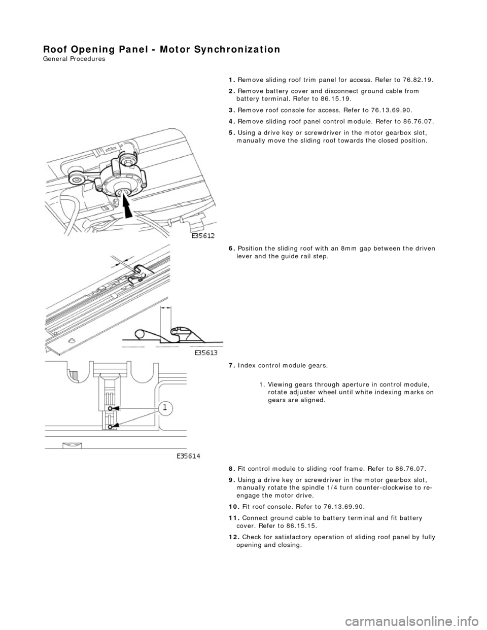
1.
Remove sliding roof trim panel for access. Refer to 76.82.19.
2. Remove battery cover and disc onnect ground cable from
battery terminal. Refer to 86.15.19.
3. Remove roof console for ac cess. Refer to 76.13.69.90.
4. Remove sliding roof panel cont rol module. Refer to 86.76.07.
5. Using a drive key or screwdriver in the motor gearbox slot,
manually move the sliding roof towards the closed position.
6. Position the sliding roof with an 8mm gap between the driven
lever and the guide rail step.
7. Index control module gears.
1. Viewing gears through aperture in control module, rotate adjuster wheel until white indexing marks on
gears are aligned.
8. Fit control module to sliding r oof frame. Refer to 86.76.07.
9. Using a drive key or screwdriver in the motor gearbox slot,
manually rotate the spindle 1/4 turn counter-clockwise to re-
engage the motor drive.
10. Fit roof console. Refer to 76.13.69.90.
11. Connect ground cable to batt ery terminal and fit battery
cover. Refer to 86.15.15.
12. Check for satisfactory operation of sliding roof panel by fully
opening and closing.