Page 2323 of 2490
10. Disconnect key interlock solenoid harness multiplug.
11. Release flasher/lamp/trip swit ch harness multiplugs from
retaining bracket and di sconnect multiplugs.
12. Disconnect cancellation module harness multiplugs.
13. Slacken and remove bolts securing switch
assemblies/cancellation module to column.
Page 2326 of 2490
8. Conne
ct key interlock solenoid harness multiplug.
9. Connect key t
ransponder exciter
coil multiplug and using new
tie straps, secure mu ltiplug to harness.
10 . Conne
ct wiper/washer switch mu
ltiplug, and fit multiplug onto
retaining bracket.
11. Fit driver side underscu ttle. Refer to 76.46.11.
12. Fit steering column uppe r cowl. Refer to 76.46.02.
13. Fit steering column lower cowl. Refer to 76.46.03
14. Fit steering wheel.
15. Fit driver airbag module. Refer to 76.73.39.
16. Fit groun
d cable to battery te
rminal and fit battery cover.
Refer to 86.15.15.
Page 2328 of 2490

Roof Opening Panel - Roof Opening Panel
Description and Operation
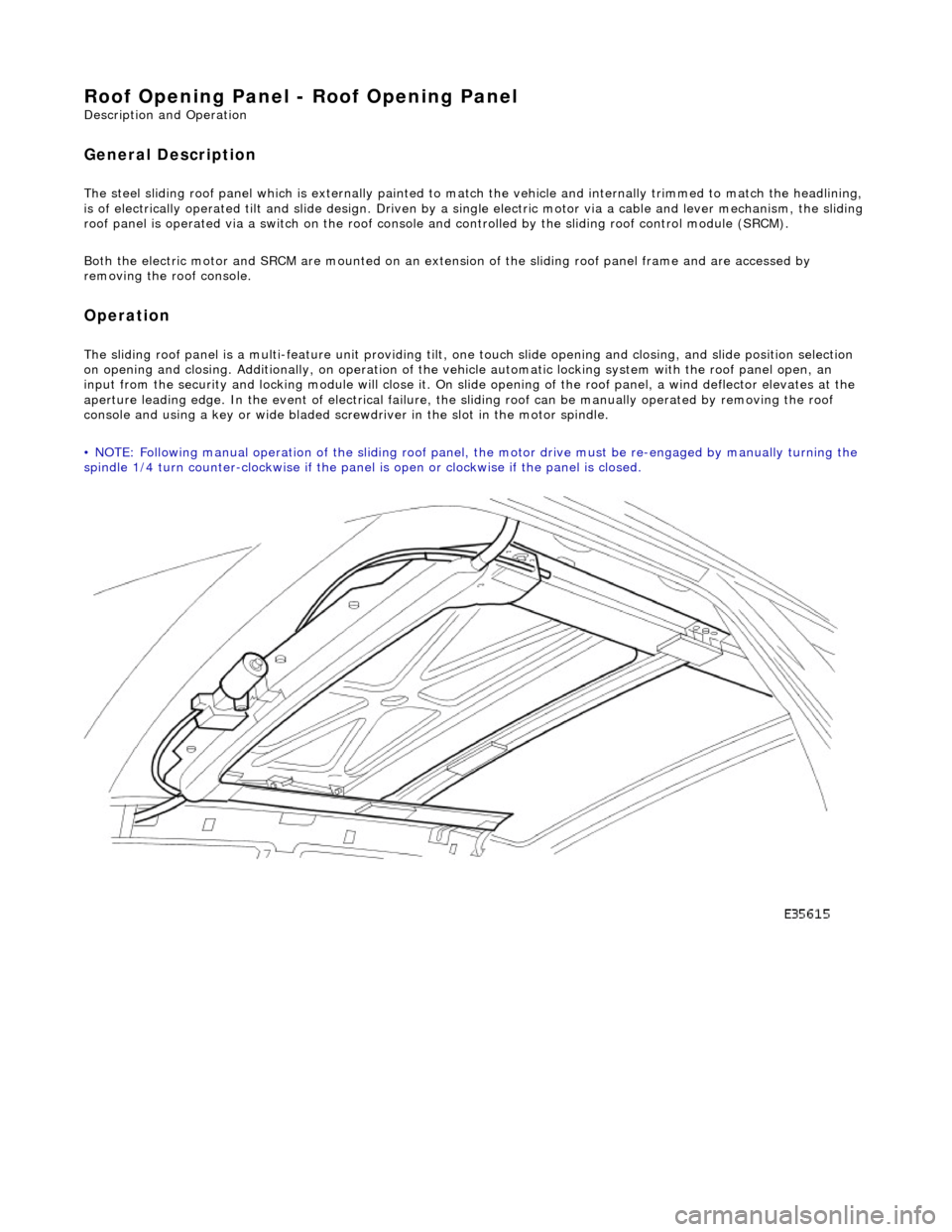
General Description
The steel sliding roof panel which is externally painted to ma tch the vehicle and internally trimmed to match the headlining,
is of electrically operated tilt and slide design. Driven by a single electric motor via a cable and lever mechanism, the slidi ng
roof panel is operated via a switch on the roof console and controlled by the sliding roof control module (SRCM).
Both the electric motor and SRCM are mounted on an extens ion of the sliding roof panel frame and are accessed by
removing the roof console.
Operation
The sliding roof panel is a multi-feature unit providing tilt, one touch slide opening and closing, and slide position selectio n
on opening and closing. Additi onally, on operation of the vehicle automatic locking system with the roof panel open, an
input from the security and lockin g module will close it. On slide opening of the roof panel, a wind deflector elevates at the
aperture leading edge. In the event of electrical failure, the sliding roof can be manually operated by removing the roof
console and using a key or wide bladed scre wdriver in the slot in the motor spindle.
• NOTE: Following manual operation of the sliding roof panel, the motor drive must be re-engaged by manually turning the
spindle 1/4 turn counter-clockwise if the panel is open or clockwise if the panel is closed.
Page 2329 of 2490

Roof Opening Panel - Motor Synchronization
General Procedures
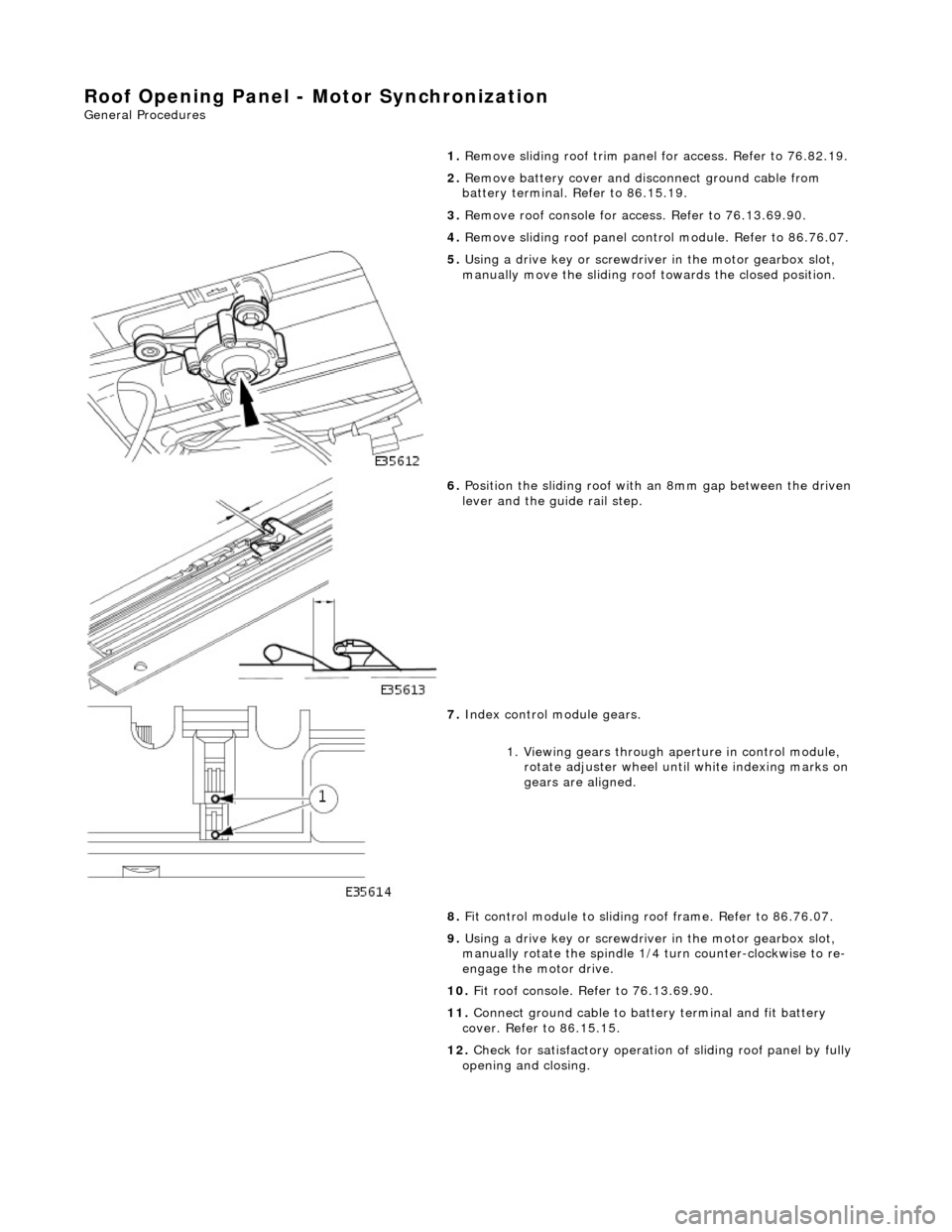
1.
Remove sliding roof trim panel for access. Refer to 76.82.19.
2. Remove battery cover and disc onnect ground cable from
battery terminal. Refer to 86.15.19.
3. Remove roof console for ac cess. Refer to 76.13.69.90.
4. Remove sliding roof panel cont rol module. Refer to 86.76.07.
5. Using a drive key or screwdriver in the motor gearbox slot,
manually move the sliding roof towards the closed position.
6. Position the sliding roof with an 8mm gap between the driven
lever and the guide rail step.
7. Index control module gears.
1. Viewing gears through aperture in control module, rotate adjuster wheel until white indexing marks on
gears are aligned.
8. Fit control module to sliding r oof frame. Refer to 86.76.07.
9. Using a drive key or screwdriver in the motor gearbox slot,
manually rotate the spindle 1/4 turn counter-clockwise to re-
engage the motor drive.
10. Fit roof console. Refer to 76.13.69.90.
11. Connect ground cable to batt ery terminal and fit battery
cover. Refer to 86.15.15.
12. Check for satisfactory operation of sliding roof panel by fully
opening and closing.
Page 2330 of 2490
Roof Opening Panel - Roof Opening Panel Alignment
General Procedures
1.
Remove sliding roof trim panel for access. Refer to 76.82.19.
2. Turn ignition switch to position II.
3. Fully close sliding roof.
4. Turn ignition switch to po sition O and remove key.
5. Slacken sliding panel to frame securing bolts.
6. Ensuring that seal is not compressed, press sliding panel
forward.
7. Align sliding panel with roof contour.
Adjust front edge of panel to align with roof contour
within -1 +0 mm.
Adjust rear edge of panel to align with roof contour
within -0 +1 mm.
8. Ensuring that roof panel settin g is not disturbed, tighten the
outer four sliding panel to frame securing bolts.
9. Insert key and turn ig nition switch to II.
10. Check for satisfactory fit and operation by opening and
closing roof panel and re -adjust as necessary.
11. Turn ignition switch to position O.
12. Tighten all sliding panel to frame securing screws
13. Fit trim panel. Refer to 76.82.19.
Page 2335 of 2490
Roof Opening Panel - Roof Opening Panel Module
Removal and Installation
Removal
1. Remove cover from battery and disconnect ground cable from
battery terminal.
2. Remove sliding roof trim panel for access. Refer to 76.82.19.
3. Using a drive key or screwdriver in the motor gearbox slot,
manually move the sliding roof towards the closed position.
4. Position the sliding roof with an 8mm gap between the driven
lever and the guide rail step.
5. Remove roof console for ac cess. Refer to 76.13.69.90.
6. Release sun visor from support and position at cantrail.
7. Remove visor support securing screw and remove support from
header.
8. Disconnect harness multiplugs from sliding roof control
module.
9. Carefully withdraw adjacent sectio n of flange finisher and edge
of headlining sufficient to prov ide access to control module.
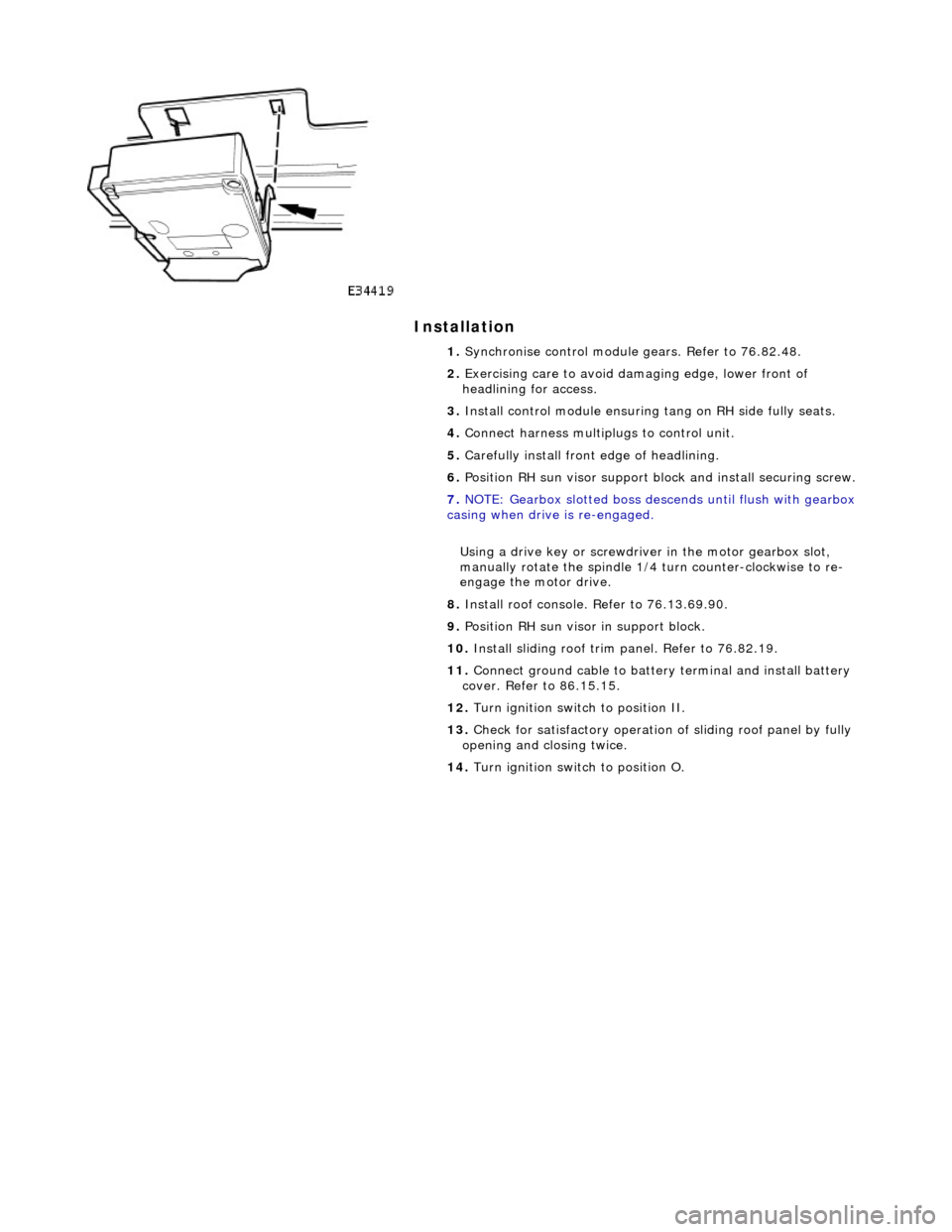
10. Depressing retaining tang on RH side of module, lower that
side and release from tang on sliding roof frame.
Page 2336 of 2490

Installation
1. Synchronise control module gears. Refer to 76.82.48.
2. Exercising care to avoid da maging edge, lower front of
headlining for access.
3. Install control module ensuring tang on RH side fully seats.
4. Connect harness multiplugs to control unit.
5. Carefully install front edge of headlining.
6. Position RH sun visor support bl ock and install securing screw.
7. NOTE: Gearbox slotted boss descends until flush with gearbox
casing when drive is re-engaged.
Using a drive key or screwdriver in the motor gearbox slot,
manually rotate the spindle 1/4 turn counter-clockwise to re-
engage the motor drive.
8. Install roof console. Refer to 76.13.69.90.
9. Position RH sun visor in support block.
10. Install sliding roof trim panel. Refer to 76.82.19.
11. Connect ground cable to batter y terminal and install battery
cover. Refer to 86.15.15.
12. Turn ignition switch to position II.
13. Check for satisfactory operation of sliding roof panel by fully
opening and closing twice.
14. Turn ignition switch to position O.
Page 2338 of 2490
3. Fit and tighten motor securing screws.
4. Connect motor harness multiplug to control module.
5. Using a drive key or screwdriver in the motor gearbox slot,
manually rotate the spindle 1/4 turn counter-clockwise to re-
engage the motor drive.
6. Fit roof console. Refer to 76.13.69.90.
7. Connect ground cable to battery terminal and fit battery cover.
Refer to 86.15.15.