Page 2377 of 2490
Supplemental Restraint System - Side Air Bag Module
Removal and Installation
Removal
• WARNINGS:
A SIDE AIR BAG MUST ONLY BE RENEWED IF A FAULT FLAG HAS OCCURRED. IN THE EVENT OF SIDE AIR BAG
DEPLOYMENT DUE TO SIDE IMPACT, THE COMPLETE SEAT MUST BE RENEWED.
FOLLOWING TEN YEARS IN SERVICE, AN AIR BAG MO DULE MUST BE REMOVED AND DISPOSED OF IN THE
APPROVED MANNER, AND A NEW AIR BAG MUST BE FITTED.
FOLLOWING DISCONNECTION OF THE BATTERY, A PERIOD OF AT LEAST FIFTEEN MINUTES MUST BE ALLOWED TO
ELAPSE BEFORE DISCONNECTING THE SINGLE-POINT SENSIN G (SPS) UNIT AND AN ELAPSE OF 2 MINUTES ALLOWED
BEFORE DISCONNECTING ANY OTHER SUPPLEMENTARY RESTRAINT SYSTEM COMPONENT.
AIR BAGS CONTAIN A CHEMICAL IRRITANT. IF AN AIR BAG IS RENEWED, THE DISCARDED UNIT MUST BE DISPOSED
OF IN ACCORDANCE WITH CURRENT SAFETY PROCEDURES.
IN THE EVENT OF A FAULT RUPTURING THE 10A BATTERY SUPPLY FUSE (F4 LOCATED IN THE FUSE-BOX AT THE
DRIVER'S END OF THE FASCIA), THE FUSE MUST NOT BE RENEWED UNTIL THE AIRBAG/SRS SYSTEM HAS BEEN DE-
ACTIVATED. FUSES OF ANY OTHER VALUE MUST NEVER BE USED, AS THIS CAN CAUSE DISARM FAILURE.
1. Remove battery cover and disc onnect ground cable from
battery terminal. Refer to 86.15.19.
2. Remove seat from vehi cle. Refer to 76.70.01.
3. Remove seat back fini sher. Refer to 76.70.09.
4. Partially remove squab cover and foam pad for access. Refer to
76.70.15
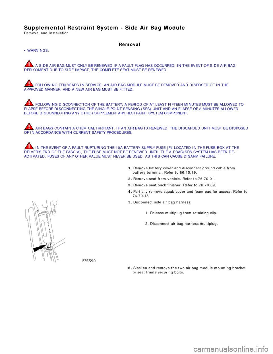
5. Disconnect side air bag harness.
1. Release multiplug from retaining clip.
2. Disconnect air ba g harness multiplug.
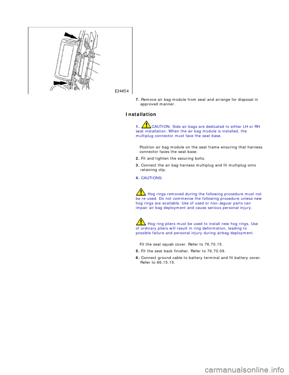
6. Slacken and remove the two air bag module mounting bracket
to seat frame securing bolts.
Page 2378 of 2490
Installation
7. Remove air bag module from seat and arrange for disposal in
approved manner.
1. CAUTION: Side air bags are de dicated to either LH or RH
seat installation. When the air bag module is installed, the
multiplug connector must face the seat base.
Position air bag module on the seat frame ensuring that harness
connector faces the seat base.
2. Fit and tighten the securing bolts.
3. Connect the air bag harness mult iplug and fit multiplug onto
retaining clip.
4. CAUTIONS:
Hog rings removed during the following procedure must not
be re-used. Do not commence the following procedure unless new hog rings are availabl e. Use of used or non-Jaguar parts can
impair air bag deployment and cause serious personal injury.
Hog ring pliers must be used to install new hog rings. Use
of ordinary pliers will result in ring deformation, leading to
possible failure and personal in jury during airbag deployment.
Fit the seat squab cover. Refer to 76.70.15.
5. Fit the seat back finisher. Refer to 76.70.09.
6. Connect ground cable to battery terminal and fit battery cover.
Refer to 86.15.15.
Page 2379 of 2490
Supplemental Restraint System - Side Impact Sensor
Removal and Installation
Removal
• WARNINGS:
FOLLOWING DISCONNECTION OF THE BA TTERY, A PERIOD OF AT LEAST FIFTEEN MINUTES MUST BE ALLOWED TO
ELAPSE BEFORE DISCONNECTING THE SINGLE-POINT SENSING (SPS) UNIT.
IN THE EVENT OF A FAULT RUPTURING THE 10A BATTER Y SUPPLY FUSE (F4 LOCATED IN THE FUSE-BOX AT THE
DRIVER'S END OF THE FASCIA), THE FUSE MUST NOT BE RENEWED UNTIL THE AIRBAG/SRS SYSTEM HAS BEEN DE-
ACTIVATED. FUSES OF ANY OTHER VALUE MUST NEVER BE USED, AS THIS CAN CAUSE DISARM FAILURE.
Installation
1. Remove battery cover and disconnect ground cable from battery
terminal. Refer to 86.15.19.
2. Remove'B' post trim pa d. Refer to 76.13.08.
3. Remove seat belt upper anchor and seat belt guide. Refer to
76.73.10
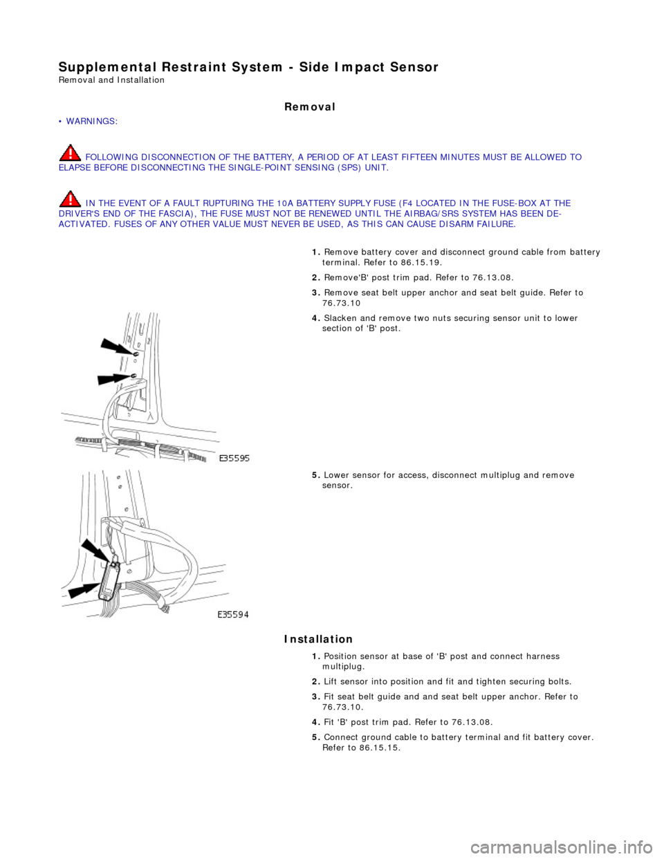
4. Slacken and remove two nuts securing sensor unit to lower
section of 'B' post.
5. Lower sensor for access, disco nnect multiplug and remove
sensor.
1. Position sensor at base of 'B' post and connect harness
multiplug.
2. Lift sensor into position and fit and tighten securing bolts.
3. Fit seat belt guide and and seat belt upper anchor. Refer to
76.73.10.
4. Fit 'B' post trim pad. Refer to 76.13.08.
5. Connect ground cable to battery terminal and fit battery cover.
Refer to 86.15.15.
Page 2421 of 2490
Uni-Body, Subframe and Mounting System - Front Axle Crossmember
Removal and Installation
Removal
CAUTION: Replacement of nuts and bolts: Various thread-locking devices are used on nuts and bolts throughout the
vehicle. These devices restrict the number of times a nut or bolt can be used. See section 100-00 for information.
Special Tool(s)
Tie-Rod-End Taper Separator
211-098 (JD 100)
Engine Support Beam
303-021 (MS 53D)
1. Position vehicle on a four-post lift.
2. Raise front of vehicle and support on stands.
3. Remove battery cover and disc onnect ground cable from
battery terminal. Refer to section 86.15.15.
4. Open hood to service position, and fit covers to fenders.
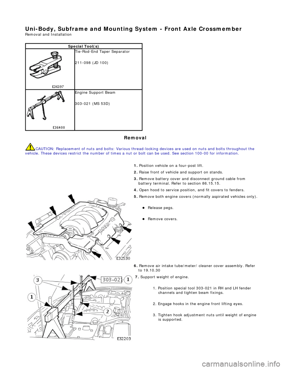
5. Remove both engine covers (nor mally aspirated vehicles only).
Release pegs.
Remove covers.
6. Remove air intake tube/meter/ cleaner cover assembly. Refer
to 19.10.30
7. Support weight of engine.
1. Position special tool 303-021 in RH and LH fender channels and tighte n beam fixings.
2. Engage hooks in the en gine front lifting eyes.
3. Tighten hook adjustment nuts until weight of engine is supported.
Page 2438 of 2490
41. Ensuring graduation mark remains aligned, finally tighten
wishbone front eccentric bolt to 113-153Nm.
42. Install air intake tube/meter/ cleaner cover assembly. Refer
to 19.10.30
43. Install both engine co vers (normally aspirated vehicles only).
Position covers over engine.
Install securing pegs.
44. Fill power steering system. Refer to Section 211-02.
45. Remove fender covers and close hood.
46. Connect ground cable to batt ery terminal and fit battery
cover. Refer 86.15.19.
47. Carry out steering geometry an d wheel alignment checks and
adjust as necessary. Refer to 57.65.03
Page 2439 of 2490
Uni-Body, Subframe and Mounting System - Front Axle Crossmember
Front Bushing
Removal and Installation
Removal
CAUTION: Replacement of nuts and bolts: Various thread-locking devices are used on nuts and bolts throughout the
vehicle. These devices restrict the number of times a nut or bolt can be used. See Section 100-00 for information.
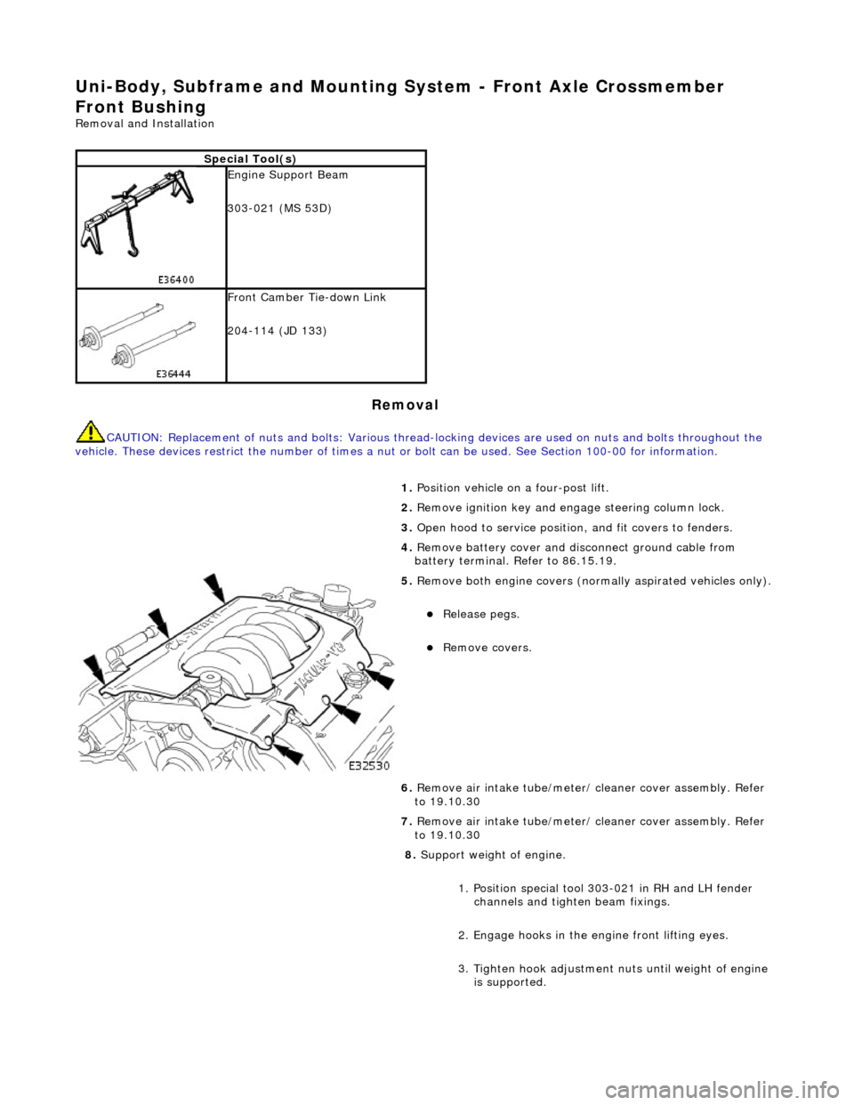
Special Tool(s)
Engine Support Beam
303-021 (MS 53D)
Front Camber Tie-down Link
204-114 (JD 133)
1. Position vehicle on a four-post lift.
2. Remove ignition key and en gage steering column lock.
3. Open hood to service position, and fit covers to fenders.
4. Remove battery cover and disc onnect ground cable from
battery terminal. Refer to 86.15.19.
5. Remove both engine covers (nor mally aspirated vehicles only).
Release pegs.
Remove covers.
6. Remove air intake tube/meter/ cleaner cover assembly. Refer
to 19.10.30
7. Remove air intake tube/meter/ cleaner cover assembly. Refer
to 19.10.30
8. Support weight of engine.
1. Position special tool 303-021 in RH and LH fender channels and tighte n beam fixings.
2. Engage hooks in the en gine front lifting eyes.
3. Tighten hook adjustment nuts until weight of engine is supported.
Page 2449 of 2490
undertray.
Install bolt and tighten to 17-23Nm.
19. Install both front road wheels. Refer to Section 204-04.
20. Raise vehicle, remove st ands and lower vehicle.
21. Remove special tool MS53 from vehicle.
22. Install both engine co vers (normally aspirated vehicles only).
Position covers over engine.
Install securing pegs.
23. Install air intake tube/meter/ cleaner cover assembly. Refer
to 19.10.30
24. Remove fender covers and close hood.
25. Connect ground cable to batt ery terminal and fit battery
cover. Refer 86.15.15.
Page 2450 of 2490
Uni-Body, Subframe and Mounting System - Front Axle Crossmember
Front Bushing Heat Shield
Removal and Installation
Removal
CAUTION: Replacement of nuts and bolts: Various thread-locking devices are used on nuts and bolts throughout the
vehicle. These devices restrict the number of times a nut or bolt can be used. See Section 100-00 for information.
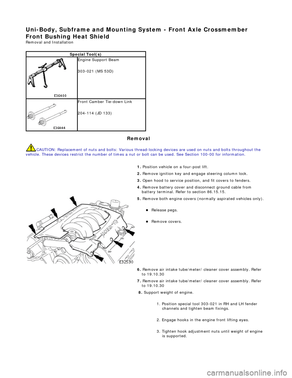
Special Tool(s)
Engine Support Beam
303-021 (MS 53D)
Front Camber Tie-down Link
204-114 (JD 133)
1. Position vehicle on a four-post lift.
2. Remove ignition key and en gage steering column lock.
3. Open hood to service position, and fit covers to fenders.
4. Remove battery cover and disc onnect ground cable from
battery terminal. Refer to section 86.15.15.
5. Remove both engine covers (nor mally aspirated vehicles only).
Release pegs.
Remove covers.
6. Remove air intake tube/meter/ cleaner cover assembly. Refer
to 19.10.30
7. Remove air intake tube/meter/ cleaner cover assembly. Refer
to 19.10.30
8. Support weight of engine.
1. Position special tool 303-021 in RH and LH fender channels and tighte n beam fixings.
2. Engage hooks in the en gine front lifting eyes.
3. Tighten hook adjustment nuts until weight of engine is supported.