Page 2362 of 2490

Safety Belt System - Front Safety Belt Retractor
Removal and Installation
Removal
• WARNINGS:
IF A SEAT BELT PRETENSIONING UNIT IS INADVERTENTLY RUPTURED AND INGESTION AND/OR INHALATION
OCCURS, FIRST AID MUST BE APPLIED AND MEDICAL ADVICE SOUGHT.
NO ATTEMPT MUST BE MADE TO DISMANTLE A PRETENSIONING RETRACTOR UNIT. THERE ARE NO SERVICEABLE
PARTS.
WHEN HANDLING A RETRACTOR UNIT PISTON HOUSING, THE PISTON MUST ALWAYS BE POINTED DOWNWARDS
AND AWAY FROM ONE'S SELF AND OTHER PERSONNEL AND FINGERS MUST BE KEPT AWAY FOM THE TAKE-UP SPOOL
MECHANISM.
ANY PRETENSIONING UNIT DROPPED FROM A HEIGHT GREA TER THAN 0.3M (12 INCHES) MUST NOT BE FITTED TO A
VEHICLE.
UNACTIVATED PRE-TENSIONING UNIT COMPONENTS CONTAIN A SOLID, FLAMMABLE MATERIAL.
1. Position seat fully forward for access.
2. Remove battery cover and disc onnect ground cable from
battery terminal. Refer to 86.15.19.
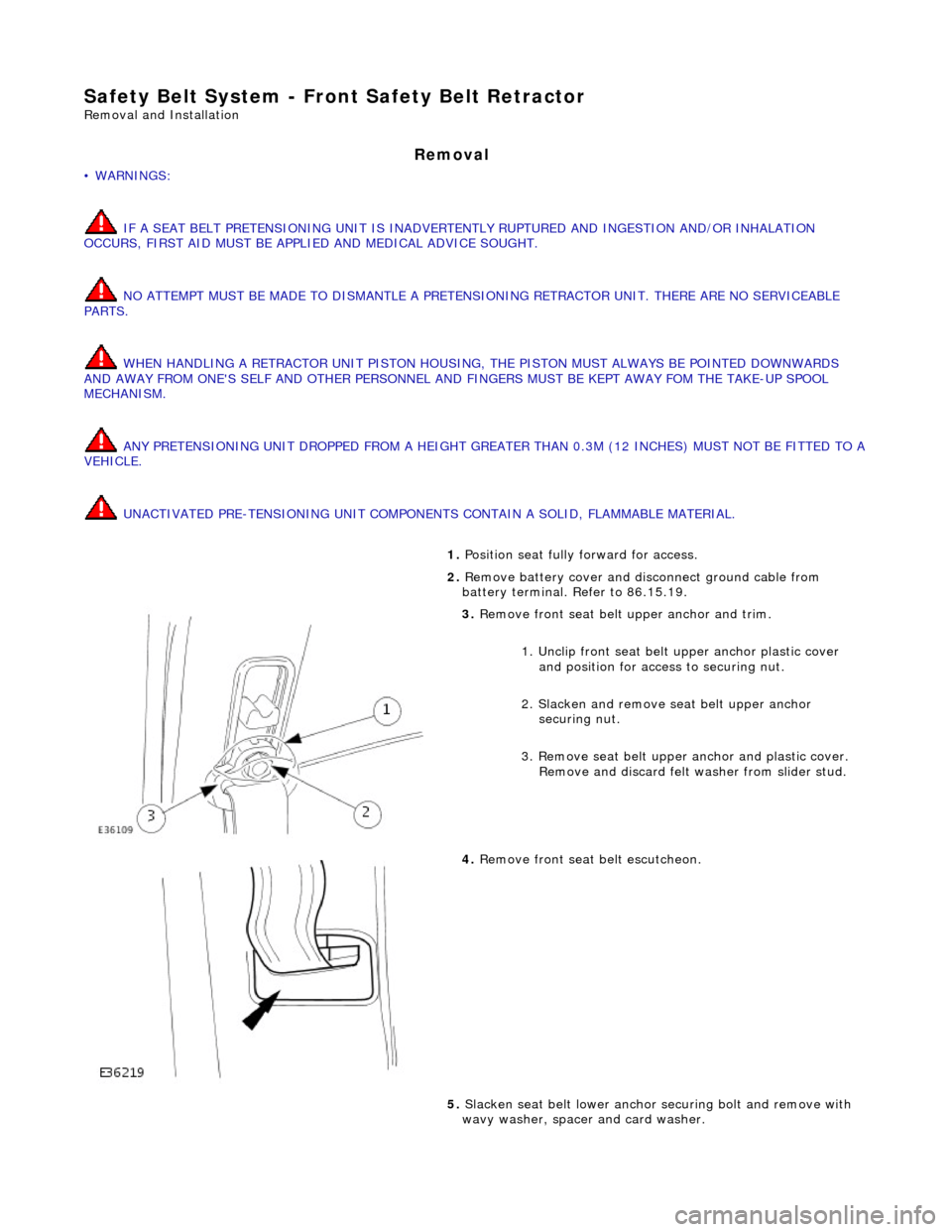
3. Remove front seat belt upper anchor and trim.
1. Unclip front seat belt upper anchor plastic cover
and position for access to securing nut.
2. Slacken and remove se at belt upper anchor
securing nut.
3. Remove seat belt upper anchor and plastic cover. Remove and discard felt washer from slider stud.
4. Remove front seat belt escutcheon.
5. Slacken seat belt lower anchor securing bolt and remove with
wavy washer, spacer and card washer.
Page 2364 of 2490
and fully tighten
securing bolts.
2. Position seat belt guide on 'B' post and fit and fully tighten the
two securing screws.
3. Position 'B' post casing in vehicle and pass seat belt anchor
plates and tongue through aperture.
4. Fit 'B' post casing. Refer to 76.13.08.
5. Fit securing bolt and wavy washer to seat belt anchor. Fit
spacer and card washer to bolt and fit and fully tighten securing
bolt.
6. Fit felt washer with paper ba cking outwards, onto height
adjuster stud
7. Position upper anchor on height adjuster stud, fit and tighten
securing nut and fit pl astic cap over nut.
8. Connect ground cable to battery terminal and fit battery cover.
Refer to 86.15.15.
9. Return seat to original position.
Page 2367 of 2490
Safety Belt System - Safety Belt Shoulder Height Adjuster
Removal and Installation
Removal
Installation
1.
Position front seat forward for access.
2. Remove battery cover and disconnect ground cable from battery
terminal. Refer to 86.15.19.
3. Remove seat belt upper anchor. Refer to 76.73.10
4. Remove 'B'post trim. Refer to 76.13.08.
5. Slacken and remove seat belt heig ht adjuster securing bolts and
remove adjuster from 'B' post.
6. Remove fibre washers, spacers an d bolts from height adjuster.
1. Fit securing bolts, spacers and fi bre washers to height adjuster.
2. Position adjuster on 'B' post an d fit and tighten securing bolts.
3. Fit 'B' post trim pad. Refer to 76.13.08.
4. Fit seat belt upper an chor. Refer to 76.73.10
5. Connect ground cable to battery terminal and fit battery cover.
Refer to 86.15.15.
Page 2371 of 2490

Supplemental Restraint System - Air Bag Control Module
Removal and Installation
Removal
Installation
1.
WARNING: FOLLOWING DISCONNECTION OF THE
BATTERY, A PERIOD OF AT LEAST ONE MINUTE MUST BE
ALLOWED TO ELAPSE BEFORE ANY WORK IS CARRIED OUT ON
AN AIR BAG SYSTEM COMPONENT.
Remove battery cover and disc onnect ground cable from
battery terminal. Refer to 86.15.19.
2. Remove 'J' gate surroun d. Refer to 76.25.24.
3. Remove centre console veneer panel. Refer to 76.47.26.
4. Remove radio. Re fer to 86.50.03.
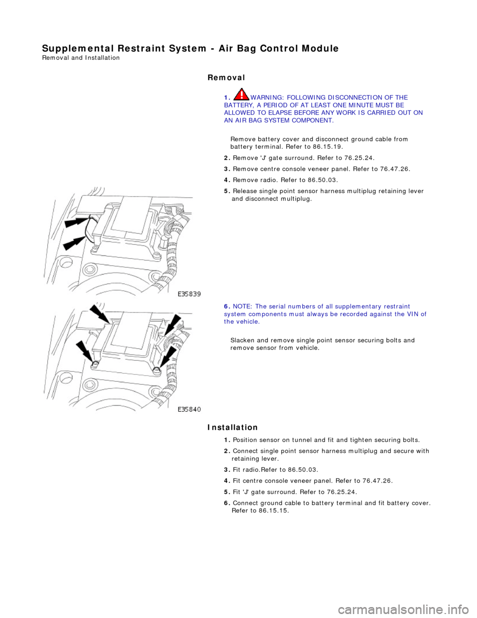
5. Release single point sensor ha rness multiplug retaining lever
and disconnect multiplug.
6. NOTE: The serial num bers of all supplementary restraint
system components must always be recorded against the VIN of
the vehicle.
Slacken and remove single point sensor securing bolts and
remove sensor from vehicle.
1. Position sensor on tunnel and fit and tighten securing bolts.
2. Connect single point sensor harn ess multiplug and secure with
retaining lever.
3. Fit radio.Refer to 86.50.03.
4. Fit centre console veneer panel. Refer to 76.47.26.
5. Fit 'J' gate surround. Refer to 76.25.24.
6. Connect ground cable to battery terminal and fit battery cover.
Refer to 86.15.15.
Page 2372 of 2490

Supplemental Restraint System - Driver Air Bag Module
Removal and Installation
Removal
• WARNINGS:
FOLLOWING DISCONNECTION OF THE BATTERY, A PERIOD OF AT LEAST ONE MINUTE MUST BE ALLOWED TO ELAPSE
BEFORE ANY WORK IS CARRIED OUT ON AN AIR BAG MODULE.
FOLLOWING TEN YEARS IN SERVICE, AN AIR BAG MO DULE MUST BE REMOVED AND DISPOSED OF IN THE
APPROVED MANNER, AND A NEW AIR BAG MUST BE FITTED.
AIR BAGS CONTAIN A CHEMICAL IRRITANT. IF AN AIR BAG IS RENEWED, THE ORIGINAL UNIT MUST BE DISPOSED
OF IN ACCORDANCE WITH CURRENT SAFETY PROCEDURES.
IN THE EVENT OF A FAULT RUPTURING THE 10A BATTERY SUPPLY FUSE (F4 LOCATED IN THE FUSE-BOX AT THE
DRIVER'S END OF THE FASCIA), THE FUSE MUST NOT BE RENEWED UNTIL THE AIRBAG/SRS SYSTEM HAS BEEN DE-
ACTIVATED. FUSES OF ANY OTHER VALUE MUST NEVER BE USED, AS THIS CAN CAUSE DISARM FAILURE.
Installation
1. Remove battery cover and disc onnect ground cable from
battery terminal. Refer to 86.15.19.
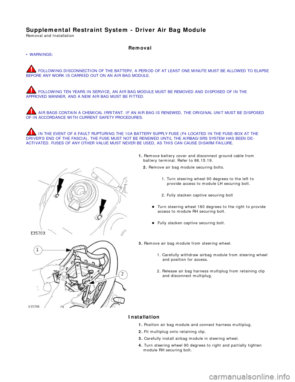
2. Remove air bag module securing bolts.
1. Turn steering wheel 90 degrees to the left to
provide access to module LH securing bolt.
2. Fully slacken captive securing bolt
Turn steering whee l 180 degrees to the right to provide
access to module RH securing bolt.
Fully slacken captive securing bolt.
3. Remove air bag module from steering wheel.
1. Carefully withdraw airbag module from steering wheel
and position for access.
2. Release air bag harness mu ltiplug from retaining clip
and disconnect multiplug.
1. Position air bag module and connect harness multiplug.
2. Fit multiplug onto retaining clip.
3. Carefully install airbag mo dule in steering wheel.
4. Turn steering wheel 90 degrees to right an d partially tighten
module RH securing bolt.
Page 2373 of 2490
5.
Turn steering wheel 90 degrees to left and partially tighten
module LH securing bolt.
6. Repeat steps 3 and 4 to fully ti ghten securing bolts and return
steering wheel to central position.
7. Fit ground cable to battery terminal. Refer to 86.15.15.
Page 2374 of 2490

Supplemental Restraint System - Passenger Air Bag Module
Removal and Installation
Removal
• WARNINGS:
FOLLOWING DISCONNECTION OF THE BATTERY, A PERIOD OF AT LEAST ONE MINUTE MUST BE ALLOWED TO ELAPSE
BEFORE ANY WORK IS CARRIED OUT ON AN AIR BAG MODULE.
FOLLOWING TEN YEARS IN SERVICE, AN AIR BAG MO DULE MUST BE REMOVED AND DISPOSED OF IN THE
APPROVED MANNER, AND A NEW AIR BAG MUST BE FITTED.
AIR BAGS CONTAIN A CHEMICAL IRRITANT. IF AN AIR BAG IS RENEWED, THE ORIGINAL UNIT MUST BE DISPOSED
OF IN ACCORDANCE WITH CURRENT SAFETY PROCEDURES.
IN THE EVENT OF A FAULT RUPTURING THE 10A BATTERY SUPPLY FUSE (F4 LOCATED IN THE FUSE-BOX AT THE
DRIVER'S END OF THE FASCIA), THE FUSE MUST NOT BE RENEWED UNTIL THE AIRBAG/SRS SYSTEM HAS BEEN DE-
ACTIVATED. FUSES OF ANY OTHER VALUE MUST NEVER BE USED, AS THIS CAN CAUSE DISARM FAILURE.
1. Remove battery cover and disc onnect ground cable from
terminal. Refer to 86.15.19.
2. Remove glove box. Refer to 76.52.03.
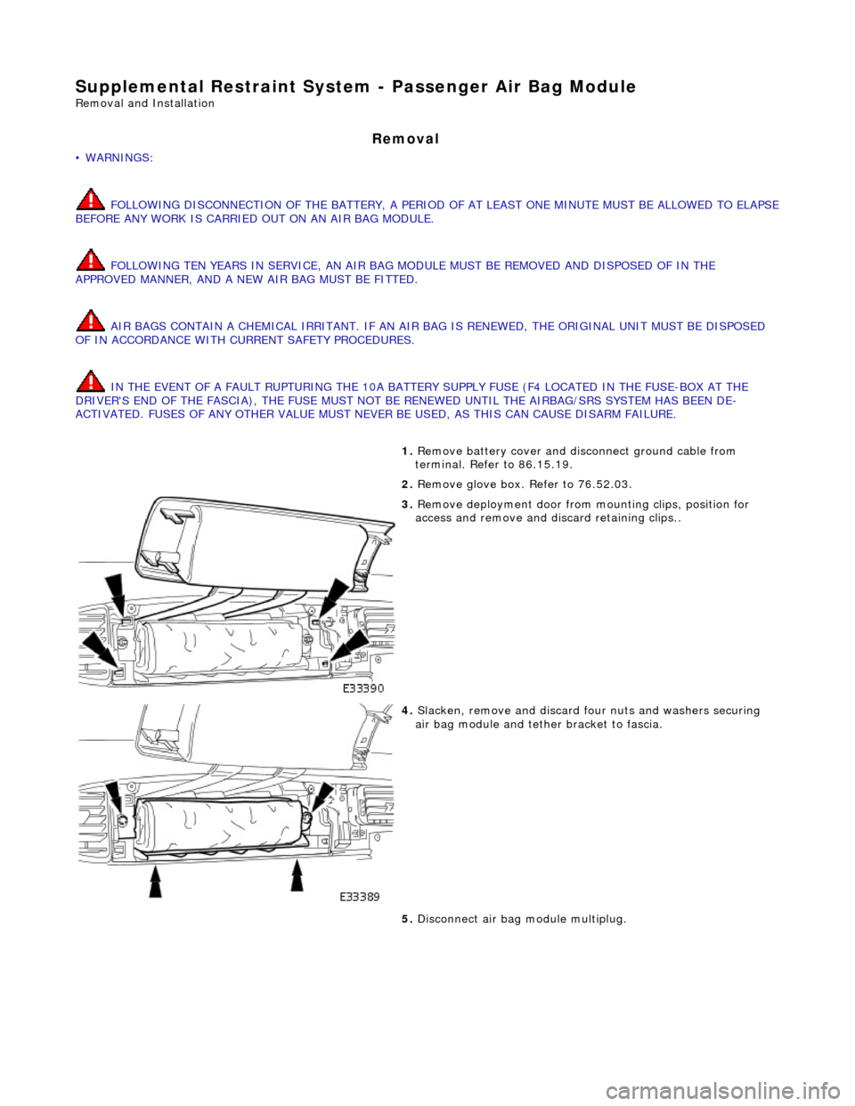
3. Remove deployment door from mounting clips, position for
access and remove and di scard retaining clips..
4. Slacken, remove and discard fo ur nuts and washers securing
air bag module and tether bracket to fascia.
5. Disconnect air bag module multiplug.
Page 2376 of 2490
module and tether bracket to fascia.
4. Connect airbag module multiplug.
5. Fit air bag deployment d oor into mounting clips.
6. Fit glove box. Refer to Section 501-05.
7. Connect ground cable to battery terminal and fit battery cover.
Refer to 86.15.15.