1998 JAGUAR X308 purge valve
[x] Cancel search: purge valvePage 1157 of 2490
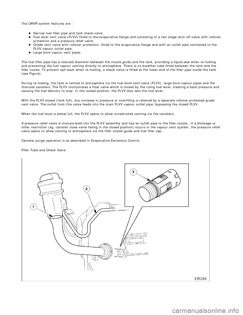
The OR
VR system features are :
N
arrow fuel filler pipe and tank check valve.
Fue
l level vent valve (FLVV) fitted to the evaporative flan
ge and consisting of a two stage shut-off valve with rollover
protection and a pressure relief valve.
Grade ven
t valve with rollover protection, fitted to the ev
aporative flange and with an outlet pipe connected to the
FLVV vapour outlet pipe.
Large bore vapour vent pipes.
The fuel filler pipe has a reduced diameter between the nozzle guide and the tank, providing a liquid seal when re-fueling
and preventing the fuel vapour venting directly to atmosphere. There is no breather tube fitted between the tank and the
filler nozzle. To prevent spit back when re-fueling, a check valv e is fitted at the lower end of the filler pipe inside the tank
(see Figure).
During re-fueling, the tank is vented to atmosphere via the fuel level vent valv e (FLVV), large bore vapour pipes and the
charcoal canisters. The FLVV incorp orates a float valve which is closed by the rising fuel level, creating a back pressure and
causing the fuel delivery to stop. In the closed position, the FLVV also sets the fuel level.
With the FLVV closed (tank full), any increase in pressure or overfilling is relieved by a separate rollover protected grade
vent valve. The outlet from this valve feeds into the main FLVV vapour outlet pipe, bypassing the closed FLVV.
When the fuel level is below full, the FLVV opens to allow unrestricted venting via the canisters.
A pressure relief valve is incorp orated into the FLVV assembly and has an outlet pipe to the filler nozzle,. If a blockage or
other restriction (eg, canister close valve failing in the closed position) occurs in the vapour vent system, the pressure reli ef
valve opens to allow venting to atmosphere via the filler nozzle guide and fuel filler cap.
Canister purge operation is as described in Evaporative Emissions Control.
Filler Tube and Check Valve
Page 1160 of 2490
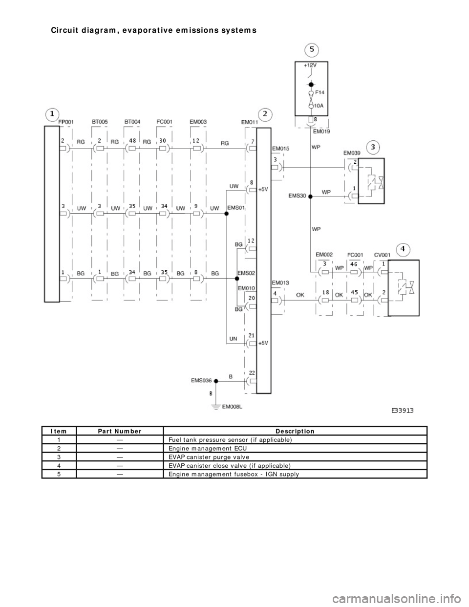
Ite
m
Part
Number
Descr
iption
1—Fu
el tank pressure sensor (if applicable)
2—Engine m
anagement ECU
3—EVAP canister purge va
lve
4—EVAP ca
nister close valve (if applicable)
5—Engine
mana
gement fusebox - IGN supply
Circuit diagram
,
evaporative emissions systems
Page 1162 of 2490
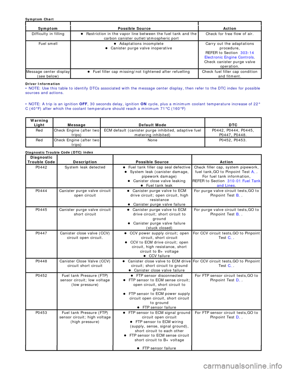
Driver Info
rmation
•
NOTE: Use this table to identify DTCs associated with the me
ssage center display, then refer to the DTC index for possible
sources and actions.
• NOTE: A trip is an ignition OFF, 30 seconds delay, ignition ON cycle, plus a minimum coolant temperature increase of 22°
C (40°F) after which the coolant temperat ure should reach a minimum 71°C (160°F)
Diagnostic Trouble C
ode (DTC) index
Sy
m
ptom
Possib
l
e Source
Acti
o
n
D
i
fficulty in filling
R
e
striction in the vapor line between the fuel tank and the
carbon canister outlet/atmospheric port
Check f or free f
low of air.
F
u
el smell
Adaptat
i
ons incomplete
Cani
st
er purge valve inoperative
Carry
o
ut the adaptations
procedure,
REFER to Section 303
-14 Ele c
tronic Engine Controls
.
Chec k cani
ster purge valve
operation.
M e
ssage center display
(see below)
Fue l
filler cap missing/not
tightened after refuelling
Check fu
el filler cap condition
and fitment.
Warning Li
ght
Mess
age Defaul
t Mode
DT
C
RedCheck Engine (after two
trip
s)
ECM de
fa
ult (canister purge inhibited, adaptive fuel
metering inhibited)
P0442,
P0444, P0445,
P0447, P0448.
Re dCheck Engine (after two
trip
s)
No
neP04 52,
P0453.
Di
agno
stic
Trouble Code
De scr
iption
Possib
l
e Source
Acti
o
n
P0442Sy
st
em leak detected
F
u
el tank filler cap seal defective
Sy
ste
m leak (c
anister damage,
pipework damage)
Cani st
er close valve leaking
F
u
el tank leak
Chec
k fi
ller cap,
system pipework,
fuel tank,GO to Pinpoint Test A.
.
F o
r fuel tank information,
REFER to Section 310
-01 Fu
el Tank
and Lines.
P0444Canist
er purge valve circuit
open circuit
Cani st
er purge valve to ECM
drive circuit; open circuit, high
resistance
Cani st
er purge valve failure
F
or purge
valve circuit tests,GO to
Pinpoint Test B.
.
P0445Canist
er purge valve circuit
short circuit
Cani st
er purge valve to ECM
drive circuit; short circuit to ground
Canist
er purge valve failure
(stuck closed)
F or purge
valve circuit tests,GO to
Pinpoint Test B.
.
P0447Canist
er close valve (CCV)
circuit open circuit.
CCV power su pply ci
rcuit; open
circuit, short circuit
CCV to ECM drive circuit;
open
circuit, high resistance, short circuit to B+ voltage
CCV failure
Fo
r CCV circuit tests,GO to Pinpoint
Test C.
.
P0448Canist
er Close Valve (CCV)
circuit short circuit
Cani st
er close valve to ECM drive
circuit; short circuit to ground
Cani st
er close valve failure
F
o
r CCV circuit tests,GO to Pinpoint
Test C.
.
P0452 Fu
el tank Pressure (FTP)
sensor circuit; low voltage (low pressure)
FTP sen
sor disconnected
FTP sen
sor to ECM sense circuit;
open circuit, short circuit to ground
FTP sens
or to ECM power supply
circuit open circuit, short circuit to ground
FT
P sensor failure
For FT
P se
nsor circuit tests,GO to
Pinpoint Test D.
.
P0453Fu
el tank Pressure (FTP)
sensor circuit; high voltage
(high pressure)
FTP sen
sor to ECM signal ground
circuit open circuit
F T
P sensor to ECM wiring
(supply, sense, signal ground),
short circuit to each other
FTP sen
sor to ECM sense circuit
short circuit to B+ voltage
For FT P se
nsor circuit tests,GO to
Pinpoint Test D.
.
FT
P sensor failure
Sym
ptom Chart
Page 1163 of 2490
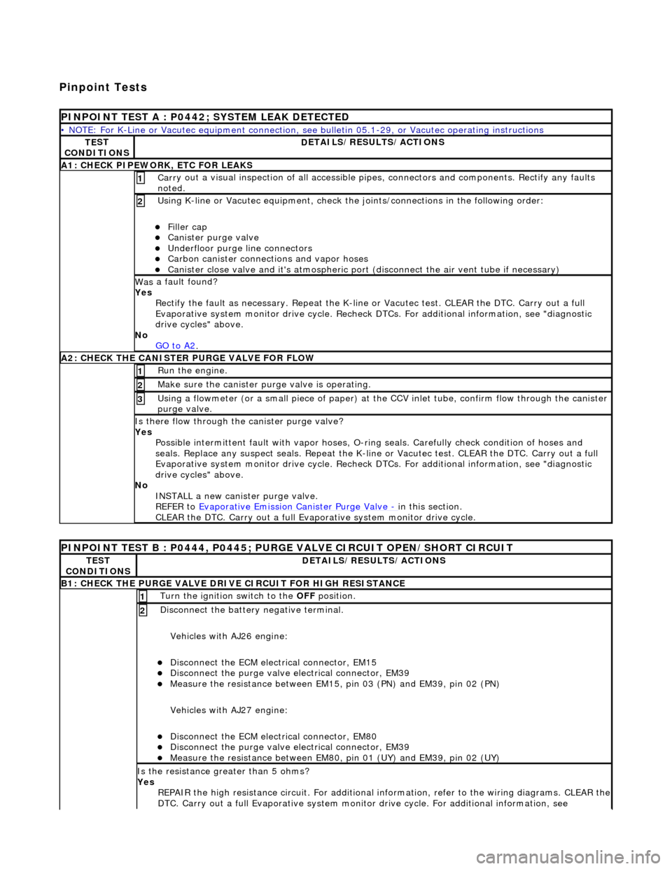
Pinpoint Tests
P
INPOINT TEST A : P0442; SYSTEM LEAK DETECTED
•
NOTE: For K-Line or Vacutec equipment connection, see bulletin 05.1-29, or Vacutec operating instructions
TE
ST
CONDITIONS
D
ETAILS/RESULTS/ACTIONS
A
1: CHECK PIPEWORK, ETC FOR LEAKS
Carr
y out a visual inspection of all accessible pipes, connectors and components. Rectify any faults
noted.
1
U
sing K-line or Vacutec equipment, check the
joints/connections in the following order:
Fi
ller cap
Cani
ster purge valve
Underfl
oor purge line connectors
Carbon
canister connections and vapor hoses
Cani
ster close valve and it's atmospheric port (disconnect the air vent tube if necessary)
2
Was
a fault found?
Yes Rectify the fault as necessary. Re peat the K-line or Vacutec test. CLEAR the DTC. Carry out a full
Evaporative system monitor drive cycle. Recheck DT Cs. For additional information, see "diagnostic
drive cycles" above.
No GO to A2
.
A2: CHECK
THE CA
NISTER PURGE VALVE FOR FLOW
Ru
n the engine.
1
Make sure the canister purge
valve is operating.
2
Using a flowmeter
(or a small piece
of paper) at the CCV inlet tube, confirm flow through the canister
purge valve.
3
Is th
ere flow through the canister purge valve?
Yes Possible intermittent faul t with vapor hoses, O-ring seals. Carefully check condition of hoses and
seals. Replace any suspect seals. Repeat the K-line or Vacutec test. CLEAR the DTC. Carry out a full
Evaporative system monitor drive cycle. Recheck DT Cs. For additional information, see "diagnostic
drive cycles" above.
No INSTALL a new canister purge valve.
REFER to Evaporative Emission Canister Purge Valve
- in t
his section.
CLEAR the DTC. Carry out a full Evap orative system monitor drive cycle.
P
INPOINT TEST B : P0444, P0445; PURGE VALVE CIRCUIT OPEN/SHORT CIRCUIT
TE
ST
CONDITIONS
D
ETAILS/RESULTS/ACTIONS
B1: CHECK
THE PURGE VALVE DRIV
E CIRCUIT FOR HIGH RESISTANCE
Turn the ignition swi
tch to the OFF
position.
1
Di
sconnect the battery negative terminal.
Vehicles with AJ26 engine:
Disc
onnect the ECM electrical connector, EM15
Di
sconnect the purge valve electrical connector, EM39
Meas
ure the resistance between EM15,
pin 03 (PN) and EM39, pin 02 (PN)
Vehicles with AJ27 engine:
Disc
onnect the ECM electrical connector, EM80
Di
sconnect the purge valve electrical connector, EM39
Meas
ure the resistance between EM80, pin 01 (UY) and EM39, pin 02 (UY)
2
Is th
e resistance greater than 5 ohms?
Yes REPAIR the high resistance circuit. For additional information, refer to the wiring diagrams. CLEAR the
DTC. Carry out a full Evaporative system monitor drive cycle. For additional information, see
Page 1164 of 2490
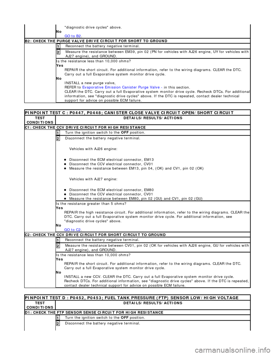
"d
iagnostic drive cycles" above.
No GO to B2
.
B2: CHECK THE PURGE VALVE DR
IV
E CIRCUIT FOR SHORT TO GROUND
Re
connect the battery negative terminal.
1
Meas
ure t
he resistance between EM39, pin 02 (PN for vehicles with AJ26
engine, UY for vehicles with
AJ27 engine), and GROUND.
2
Is t
he resistance less than 10,000 ohms?
Yes REPAIR the short circuit. For addi tional information, refer to the wiring diagrams. CLEAR the DTC.
Carry out a full Evaporative system monitor drive cycle.
No INSTALL a new purge valve,
REFER to Evaporative Emission Canister Purge Valve
- in thi
s section.
CLEAR the DTC. Carry out a full Evaporative system monitor drive cycle. Recheck DTCs. For additional
information, see "diagnostic drive cycles" above. If the DTC is repeated, contact dealer technical
support for advice on possible ECM failure.
PI
NPOINT TEST C : P0447, P0448; CANISTER CLOSE VALVE CIRCUIT OPEN/SHORT CIRCUIT
TE
S
T
CONDITIONS
D E
TAILS/RESULTS/ACTIONS
C1
: CH
ECK THE CCV DRIVE CIRCUIT FOR HIGH RESISTANCE
Turn the ignition swi
t
ch to the
OFF position.
1
Disc
onnect the battery negative terminal.
Vehicles with AJ26 engine:
Disc onne
ct the ECM electrical connector, EM13
Di
sc
onnect the CCV electrical connector, CV01
Meas
ure t
he resistance between EM13, pi
n 04, (OK) and CV1, pin 02 (OK)
Vehicles with AJ27 engine:
Disc onne
ct the ECM electrical connector, EM80
Di
sc
onnect the CCV electrical connector, CV01
Meas
ure t
he resistance between EM80,
pin 02 (GU) and CV1, pin 02 (GU)
2
Is the res
istance greater than 5 ohms?
Yes REPAIR the high resistance circuit. For additional information, refer to the wiring diagrams. CLEAR the
DTC. Carry out a full Evaporative system monitor drive cycle. For additional information, see
"diagnostic drive cycles" above.
No GO to C2
.
C2: CH
ECK THE CCV DRIVE CIRCUI
T FOR SHORT CIRCUIT TO GROUND
Re
connect the battery negative terminal.
1
Meas
ure t
he resistance between CV01,
pin 02 (OK for vehicles with AJ26 engine, GU for vehicles with
AJ27 engine), and GROUND.
2
Is t
he resistance less than 10,000 ohms?
Yes REPAIR the short circuit. For addi tional information, refer to the wiring diagrams. CLEAR the DTC.
Carry out a full Evaporative system monitor drive cycle.
No INSTALL a new CCV. CLEAR the DTC. Carry out a fu ll Evaporative system monitor drive cycle.
Recheck DTCs. For additional inform ation, see "diagnostic drive cycles" above. If the DTC is repeated,
contact dealer technical support for advice on possible ECM failure.
P INPOINT TES
T D : P0452, P0453; FUEL TANK
PRESSURE (FTP) SENSOR LOW/HIGH VOLTAGE
TES
T
CONDITIONS
DE
TAILS/RESULTS/ACTIONS
D
1:
CHECK THE FTP SENSOR SENSE CIRCUIT FOR HIGH RESISTANCE
Turn the ignition swi
t
ch to the OFF
position.
1
Disc
onnect the battery negative terminal.
2
Page 1169 of 2490
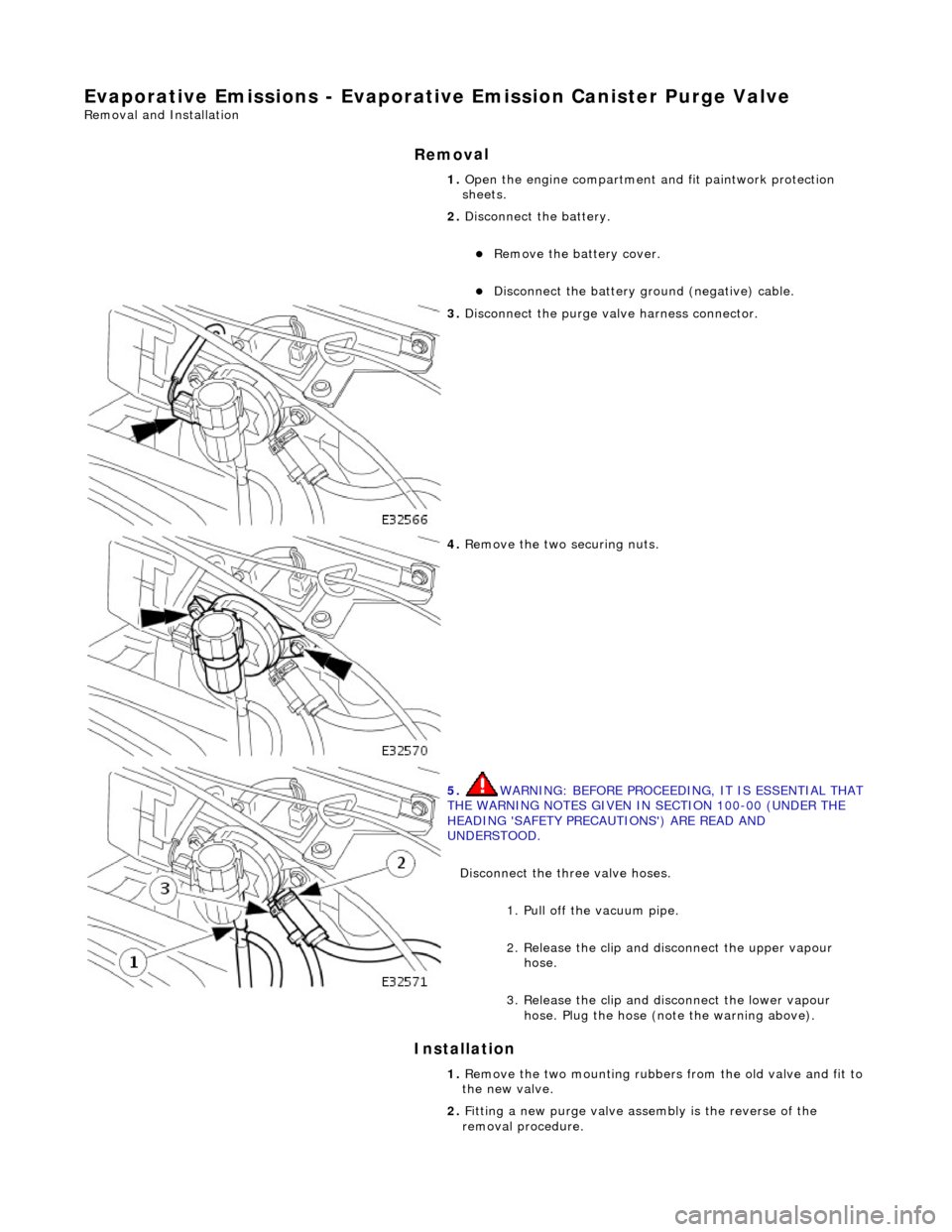
Evaporative Emissions - Evaporative Emission Canister Purg
e Valve
Re
moval and Installation
Remov
al
Installation
1. O
pen the engine compartment and fit paintwork protection
sheets.
2. Disconnect the battery.
R
emove the battery cover.
Di
sconnect the battery ground (negative) cable.
3. Di
sconnect the purge valve harness connector.
4. R
emove the two securing nuts.
5. WARNING: B
EFORE PROCEEDING, IT IS ESSENTIAL THAT
THE WARNING NOTES GIVEN IN SECTION 100-00 (UNDER THE
HEADING 'SAFETY PRECAUTIONS') ARE READ AND
UNDERSTOOD.
Disconnect the three valve hoses.
1. Pull off the vacuum pipe.
2. Release the clip and di sconnect the upper vapour
hose.
3. Release the clip and disconnect the lower vapour hose. Plug the hose (note the warning above).
1. R
emove the two mounting rubbers from the old valve and fit to
the new valve.
2. Fitting a new purge valve asse mbly is the reverse of the
removal procedure.
Page 1190 of 2490
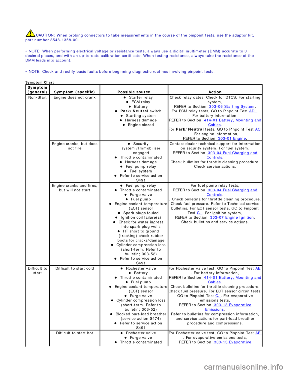
CAUTIO
N: When probing connectors to take
measurements in the course of the pinpoint tests, use the adaptor kit,
part number 3548-1358-00.
• NOTE: When performing electrical voltag e or resistance tests, always use a digital multimeter (DMM) accurate to 3
decimal places, and with an up-t o-date calibration certificate. When testing resistance, always take the resistance of the
DMM leads into account.
• NOTE: Check and rectify basic faults before beginning diagnostic ro utines involving pinpoint tests.
Sym
ptom Chart
Sym
ptom
(general)
S y
mptom (specific)
Possib
l
e source
Acti
o
n
No
n
-Start
Engine
does not cran
k
Starter relay ECM relay Batt
ery Park
/Neutral
switch
Starting system
Harness damage
Engine s
iezed
Check r
e
lay dates. Check
for DTCS. For starting
system,
REFER to Section 303
-06 Sta r
ting System
.
F or ECM
relay tests, GO to Pinpoint Test
AD.
.
F o
r battery information,
REFER to Section 414
-0 1
Battery, Mounting and
Cables.
Fo r
Park/Neutral tests, GO to Pinpoint Test AC.
. Fo
r engine information,
REFER to Section 303
-01 En
gine
.
Engine cranks, but does
not fireSecurity
syst
em /Immobiliser
engaged
Thr o
ttle contaminated
Harness damage
Fu
el pump relay
Fue
l
system
R
e
fer to service action
S491
Contact dealer techni
cal
support for information
on security system. For fuel system,
REFER to Section 303
-0 4
Fuel Charging and
Controls.
Check bull etins for throttl
e cleaning procedure.
Check service actions.
Engine cranks an d
fires,
but will not start
F u
el pump relay
Thr
o
ttle contaminated
Purge
val
ve
Fue
l
pump
Engine coolan
t
temperature
(ECT) sensor
Spark plugs
fouled
Ignition coil
fail
ure(s)
Check f
o
r water ingress
into spark plug wells
HT sh o
rt to ground
(tracking) check rubber
boots for cracks/damage
Cyli
nder compression loss
(short-term. Refer to bulletin; 303-52)
Re
fer to service action
S491
Fo
r fuel pump relay tests,
REFER to Section 303
-0 4
Fuel Charging and
Controls.
. Check bulletins for throttl
e cleaning procedure.
Check fuel pressure. Refe r to Technical service
bulletins. For ECT sensor tests, GO to Pinpoint Test C.
. Fo
r ignition system,
REFER to Section 303
-07 En
gine Ignition
.
Check bulletins an d service a
ctions.
Di
f
ficult to
start
D iff
icult to start cold
Roc
h
ester valve
Batt
ery Thro
ttle contaminated
Fue
l
pump
Engine coolan
t
temperature
(ECT) sensor
Purge val
ve
Cyl
i
nder compression loss
(short-term. Refer to bulletin; 303-52)
Blocked part-load breather (s
ervice action S474)
R
e
fer to service action
S491
For R
ochester valv
e test, GO to Pinpoint Test AE.
. Fo
r battery information,
REFER to Section 414
-0 1
Battery, Mounting and
Cables.
Check bull etins for throttl
e cleaning procedure.
Check fuel pressure. For ECT sensor circuit tests,
GO to Pinpoint Test C.
. F
or evaporative
emissions tests,
REFER to Section 303
-1 3
Evaporative
Emiss
i
ons
.
R e
fer to bulletins for co
mpression information,
and service actions for part-load breather procedure and compressions.
Diff
icult to start hot
Roc
h
ester valve
Purge
val
ve
Thr
o
ttle contaminated
F
or R
ochester valv
e test, GO to Pinpoint Test AE.
. F
or evaporative emissions tests,
REFER to Section 303
-1 3
Evaporative
Page 1191 of 2490
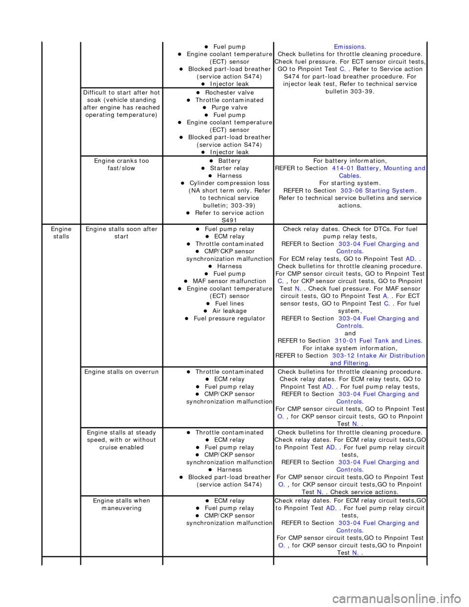
Fue
l pump
Engine coolan
t temperature
(ECT) sensor
Blocked part-load breather (
service action S474)
Injec
tor leak
Emiss
ions
.
Check bull
etins for throttle cleaning procedure.
Check fuel pressure. For ECT sensor circuit tests,
GO to Pinpoint Test C.
. Refer to Servi
ce action
S474 for part-load breather procedure. For
injector leak test, Refer to technical service bulletin 303-39.
D
ifficult to start after hot
soak (vehicle standing
after engine has reached operating temperature)
Roc
hester valve
Thr
ottle contaminated
Purge
valve
Fue
l pump
Engine coolan
t temperature
(ECT) sensor
Blocked part-load breather (
service action S474)
Injec
tor leak
Engine cranks too
fa
st/slow
Batt
ery
Starter relay Harness Cyl
inder compression loss
(NA short term only. Refer to technical service bulletin; 303-39)
R
efer to service action
S491
F
or battery information,
REFER to Section 414
-0
1 Battery, Mounting and
Cables.
F
or starting system.
REFER to Section 303
-06 Sta
rting System
.
R
efer to technical servic
e bulletins and service
actions.
Engine
stalls
Engine st
alls soon after
start
F
uel pump relay
ECM relay Thr
ottle contaminated
CMP/CKP sen
sor
synchronization malfunction
Harness Fue
l pump
MAF
sensor malfunction
Engine coolan
t temperature
(ECT) sensor
Fue
l lines
Air leakage
F
uel pressure regulator
Check r
elay dates. Chec
k for DTCs. For fuel
pump relay tests,
REFER to Section 303
-0
4 Fuel Charging and
Controls.
F
or ECM relay tests, GO to Pinpoint Test
AD.
.
Check bull
etins for throttle cleaning procedure.
For CMP sensor circuit test s, GO to Pinpoint Test
C.
, for
CKP sensor circuit tests, GO to Pinpoint
Test N.
. Check fuel
pressure. For MAF sensor
circuit tests, GO to Pinpoint Test A.
. For EC
T
sensor tests, GO to Pinpoint Test C.
. F
or fuel
system,
REFER to Section 303
-0
4 Fuel Charging and
Controls.
and
REF
ER to Section 310
-0
1 Fuel Tank and Lines
. F
or intake system information,
REFER to Section 303
-1
2 Intake Air Distribution
and F
iltering
.
Engine
stalls on overrun
Thr
ottle contaminated
ECM relay F
uel pump relay
CMP/CKP sen
sor
synchronization malfunction
Check bull
etins for throttle cleaning procedure.
Check relay dates. For ECM relay tests, GO to Pinpoint Test AD.
. F
or fuel pump relay tests,
REFER to Section 303
-0
4 Fuel Charging and
Controls.
F
or CMP sensor circuit test
s, GO to Pinpoint Test
O.
, for
CKP sensor circuit tests, GO to Pinpoint
Test N.
.
E
ngine stalls at steady
speed, with or without cruise enabled
Thr
ottle contaminated
ECM relay F
uel pump relay
CMP/CKP sen
sor
synchronization malfunction
Harness Blocked part-load breather
(
service action S474)
Check bull
etins for throttle cleaning procedure.
Check relay dates. For EC M relay circuit tests,GO
to Pinpoint Test AD.
. F
or fuel pump relay circuit
tests,
REFER to Section 303
-0
4 Fuel Charging and
Controls.
F
or CMP sensor circuit test
s,GO to Pinpoint Test
O.
, for
CKP sensor circuit tests,GO to Pinpoint
Test N.
. Che
ck service actions.
Engine st
alls when
maneuvering
ECM relay F
uel pump relay
CMP/CKP sen
sor
synchronization malfunction
Check r
elay dates. For EC
M relay circuit tests,GO
to Pinpoint Test AD.
. F
or fuel pump relay circuit
tests,
REFER to Section 303
-0
4 Fuel Charging and
Controls.
F
or CMP sensor circuit test
s,GO to Pinpoint Test
O.
, for
CKP sensor circuit tests,GO to Pinpoint
Test N.
.