1998 JAGUAR X308 oil filter
[x] Cancel search: oil filterPage 1759 of 2490

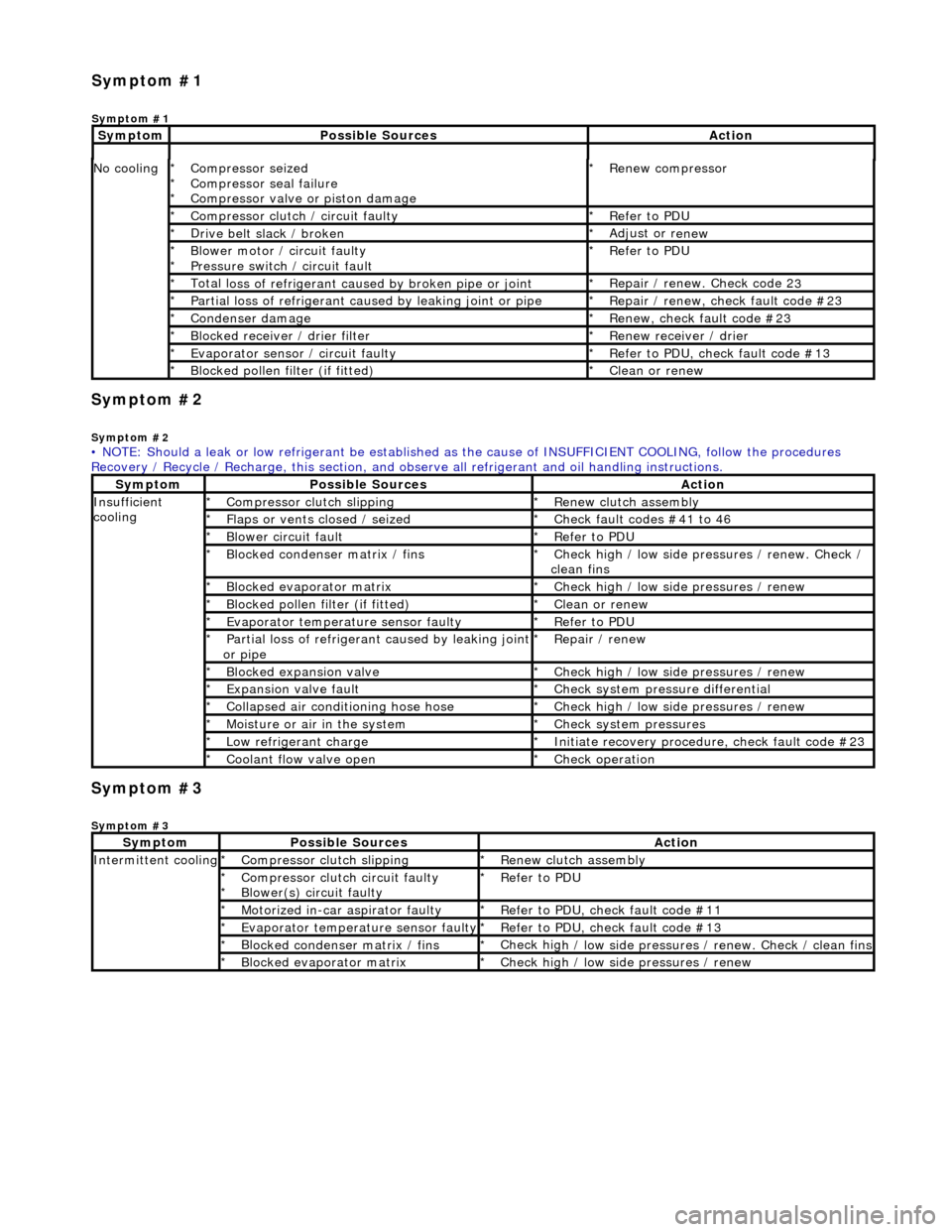
Sym
ptom #2
Sy
mptom #2
Sym
ptom #3
Sy
mptom #3
No
cooling
Compressor sei
zed
Compressor seal failure
Compressor valve or piston damage
*
*
*
R
enew compressor
*
Compressor cl
utch / circuit faulty
*
R
efer to PDU
*
D
rive belt slack / broken
*
Adjust or r
enew
*
B
lower motor / circuit faulty
Pressure switch / circuit fault
*
*
R
efer to PDU
*
Total l
oss of refrigerant caused by broken pipe or joint
*
Repair / renew. Check code 2
3
*
P
artial loss of refrigerant caused by leaking joint or pipe
*
R
epair / renew, check fault code #23
*
Conden
ser damage
*
Re
new, check fault code #23
*
Bl
ocked receiver / drier filter
*
R
enew receiver / drier
*
Evaporator senso
r / circuit faulty
*
R
efer to PDU, check fault code #13
*
Bl
ocked pollen filter (if fitted)
*
Cle
an or renew
*
• NOTE: Should a leak or low refrigerant be established as the cause of INSUFFICIENT COOL ING, follow the procedures
Recovery / Recycle / Recharge, this section, and ob serve all refrigerant and oil handling instructions.
Sy
mptom
Possib
le Sources
Acti
on
Insuffi
cient
cooling
Compre
ssor clutch slipping
*
R
enew clutch assembly
*
Fl
aps or vents closed / seized
*
Check f
ault codes #41 to 46
*
Bl
ower circuit fault
*
R
efer to PDU
*
Bl
ocked condenser matrix / fins
*
Check hig
h / low side pr
essures / renew. Check /
clean fins
*
Bl
ocked evaporator matrix
*
Check hig
h / low side
pressures / renew
*
Bl
ocked pollen filter (if fitted)
*
Cle
an or renew
*
Evaporator temp
erat
ure sensor faulty
*
R
efer to PDU
*
P
artial loss of refrigerant caused by leaking joint
or pipe
*
R
epair / renew
*
Blocked expan
sion valve
*
Check hig
h / low side
pressures / renew
*
Expans
ion valve fault
*
Chec
k system pres
sure differential
*
C
ollapsed air conditioning hose hose
*
Check hig
h / low side
pressures / renew
*
Moi
sture or air in the system
*
Chec
k system pressures
*
Low r
efrigerant charge
*
Initiate recovery
procedure, check fault code #23
*
Coo
lant flow valve open
*
Chec
k operation
*
Sy
mptom
Possib
le Sources
Acti
on
Int
ermittent cooling
Compre
ssor clutch slipping
*
R
enew clutch assembly
*
Compressor cl
utch circuit faulty
Blower(s) circuit faulty
*
*
R
efer to PDU
*
Motorized in-car aspirator faulty
*
R
efer to PDU, check fault code #11
*
Evaporator temp
erature sensor faulty
*
R
efer to PDU, check fault code #13
*
Bl
ocked condenser matrix / fins
*
Check hig
h / low side pressures / renew. Check / clean fins
*
Bl
ocked evaporator matrix
*
Check hig
h / low side
pressures / renew
*
Sym
ptom #1
Sy
mptom #1
Sy
mptom
Possib
le Sources
Acti
on
Page 1760 of 2490

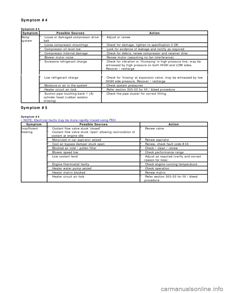
Symp
tom #5
Sy
m
ptom #5
Low r
e
frigerant charge
*
Check f or 'hissi
ng' at expansion
valve; may be witnessed by low
HIGH side pressure. Recover / recharge
*
Moi
s
ture or air in the system
*
Chec k syst
em pressures
*
Heat er ci
rcuit air-lock
*
R e
fer section 303-03 for fill / bleed procedure
*
Suct ion
pipe touching bank 1 (A)
cylinder head (rubber isolator
missing)
*
Check the pi
pe cluster for correct fitti
ng
*
• NOTE: Electrical faults may be more rapidly traced using PDU
Sym
ptom
Possib
l
e Sources
Acti
o
n
Insuffi
ci
ent
heating
Coo l
ant flow valve stuck 'closed'
Coolant flow valve stuck 'open' allowing recirculation of
coolant at engine idle
*
*
Re
new v
alve
*
Motorized in-car aspirator sei zed
*R e
new aspirator
*
Coo l
air bypass damper stuck open
*
Re new,
check fault code #43
*
B l
ocked air inlet / pollen filter
*
Chec k / cl
ean / renew
*
B l
ower speed low
*
Check performance range
*
Low cool ant
level
*
Adjust as req u
ired (verify and correct
reason for loss)
*
Engine
t
hermostat faulty
*
Check engine r u
nning temperature
*
Heater water pump seized
*Chec k op
eration
*
Heater ma trix
blocked
*
Re new m
atrix
*
Heater circui t
air-lock
*
R e
fer section 303-03 for fill / bleed
procedure
*
Sym
p
tom #4
Sym
ptom #4
Sy
m
ptom
Possib
l
e Sources
Acti
o
n
No
i
sy
system
Loose or damaged compressor drive
belt
*Adjust or r
e
new
*
Loose compressor mountings
*Check f o
r damage, tighten to specification if OK
*
Compressor oil level l
ow
*
Look for evidence of l
eakag
e and rectify as required
*
Compressor internal dama ge
*Check f o
r debris, renew compressor and receiver drier
*
B l
ower motor noise
*
Re new m
otor (assuming no fan interference)
*
Excessive refrige rant charge
*Check f o
r vibration or 'thumping'
in high pressure line; may be
witnessed by high pressure on both HIGH and LOW sides.
Recover / recharge
*
Page 2383 of 2490

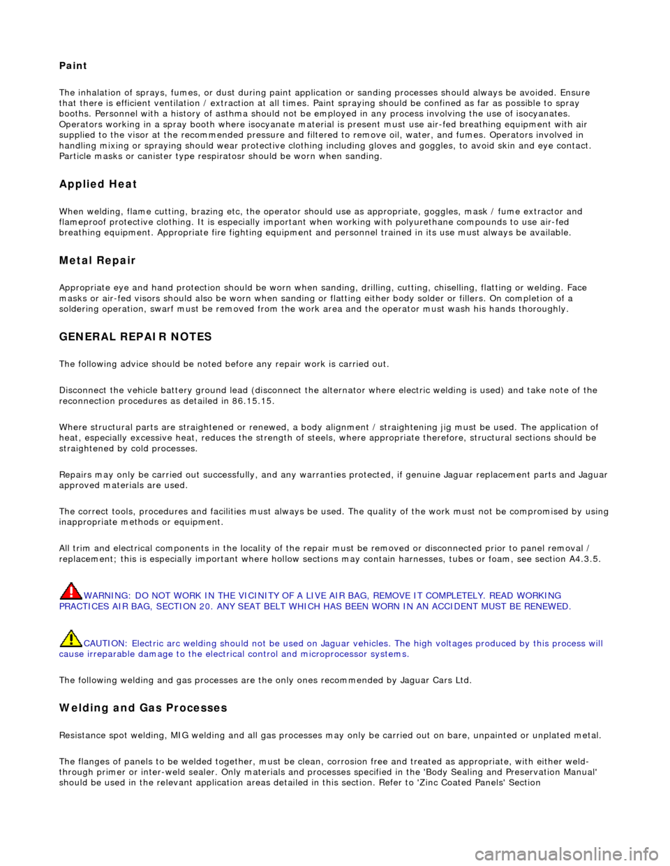
Paint
The inhalation of sprays, fumes, or dust during paint application or sanding processes should always be avoided. Ensure
that there is efficient ventilation / extrac tion at all times. Paint spraying should be confined as far as possible to spray
booths. Personnel with a history of asth ma should not be employed in any process involving the use of isocyanates.
Operators working in a spray booth where isocyanate material is present must use air-fed breathing equipment with air
supplied to the visor at the re commended pressure and filtered to remove oil, water, and fumes. Operators involved in
handling mixing or spraying should wear protective clothing including gloves and goggles, to avoid skin and eye contact.
Particle masks or canister type respir atosr should be worn when sanding.
Applied Heat
When welding, flame cutting, brazing etc, the operator shou ld use as appropriate, goggles, mask / fume extractor and
flameproof protective clothing. It is especially important when working with polyurethane compounds to use air-fed
breathing equipment. Appropriat e fire fighting equipment and personnel trai ned in its use must always be available.
Metal Repair
Appropriate eye and hand protection should be worn when sanding, drilling, cutting, chiselling, flatting or welding. Face
masks or air-fed visors should also be wo rn when sanding or flatting either body solder or fillers. On completion of a
soldering operation, swarf must be re moved from the work area and the operat or must wash his hands thoroughly.
GENERAL REPAIR NOTES
The following advice should be noted before any repair work is carried out.
Disconnect the vehicle battery gr ound lead (disconnect the alternator where electric welding is used) and take note of the
reconnection procedures as detailed in 86.15.15.
Where structural parts are straightened or renewed, a body alignment / straightening jig must be used. The application of
heat, especially excessive heat, reduces the strength of steels, where appropriate therefore, structural sections should be
straightened by cold processes.
Repairs may only be carried out successful ly, and any warranties protected, if genuine Jaguar replacement parts and Jaguar
approved materials are used.
The correct tools, procedures and facilities must always be us ed. The quality of the work must not be compromised by using
inappropriate methods or equipment.
All trim and electrical components in the locality of the repair must be removed or disconnected prior to panel removal /
replacement; this is especially important where hollow sectio ns may contain harnesses, tubes or foam, see section A4.3.5.
WARNING: DO NOT WORK IN THE VICINITY OF A LIVE AIR BAG, REMOVE IT COMPLETELY. READ WORKING
PRACTICES AIR BAG, SECTION 20. ANY SEAT BELT WHICH HAS BEEN WORN IN AN ACCIDENT MUST BE RENEWED.
CAUTION: Electric arc welding should not be used on Jaguar vehicles. The high voltages produced by this process will
cause irreparable damage to the electric al control and microprocessor systems.
The following welding and gas processes are the only ones recommended by Jaguar Cars Ltd.
Welding and Gas Processes
Resistance spot welding, MIG welding and all gas processes may only be carried out on bare, unpainted or unplated metal.
The flanges of panels to be welded toge ther, must be clean, corrosion free and tr eated as appropriate, with either weld-
through primer or inter-weld sealer. Only materials and processes specified in the 'Body Sealing and Preservation Manual'
should be used in the relevant application areas detailed in this section. Refer to 'Zinc Coated Panels' Section