Page 102 of 2490

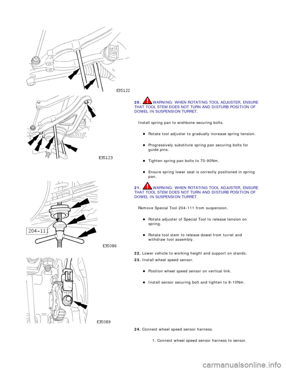
20. WARNING: WHE
N ROTATING TOOL ADJUSTER, ENSURE
THAT TOOL STEM DOES NOT TU RN AND DISTURB POSITION OF
DOWEL IN SUSPENSION TURRET.
Install spring pan to wishbone securing bolts.
Ro t
ate tool adjuster to gradua
lly increase spring tension.
Pr
ogressively substitute spri
ng pan securing bolts for
guide pins.
Tighten spring pan
bolts to 70-90Nm.
Ensure spri
ng
lower seat is co
rrectly positioned in spring
pan.
21 . WARNING: WHE
N ROTATING TOOL ADJUSTER, ENSURE
THAT TOOL STEM DOES NOT TU RN AND DISTURB POSITION OF
DOWEL IN SUSPENSION TURRET.
Remove Special Tool 204-111 from suspension.
Rotat
e adjuster of Special Tool to release tension on
spring.
R o
tate tool stem to release dowel from turret and
withdraw tool assembly.
22 . Lower vehi
cle to working heig
ht and support on stands.
23 . Inst
all wheel speed sensor.
Posi
ti
on wheel speed sensor on vertical link.
Instal
l sensor securing bolt
and tighten to 8-10Nm.
24. Connect wheel speed sensor harness.
1. Connect wheel speed sensor harness to sensor.
Page 103 of 2490
2.
Using new tiestraps secure wheel speed sensor
harness to upper wishbone.
25
.
Install brake calipers.
R
emove tie supporting brake caliper.
1. Install caliper on carrier.
2. Install guide pins and tighten to 25-30Nm.
3. Install guide pin dust caps.
4. Install caliper spring clip.
26
.
Position and partially tighten wishbone rear eccentric bolt.
R
otate eccentric bolt to align large graduation with mark
made during removal.
27
.
Position and partially tighten wishbone front eccentric bolt.
R
otate eccentric bolt to align large graduation with mark
made during removal.
P
artially tighten bolt.
28. Fit road wheel. Refer to Section 100-02.
29. Raise vehicle, remove stands and lower vehicle onto road
wheels.
30. Ensuring graduation mark remains aligned, finally tighten
wishbone rear eccentric bolt to 113-153Nm.
Page 130 of 2490
positio
n.
6. Raise front of vehicle and support on stands. refer to Section
100-02.
7. Remove appropriate road wheel. Refer to Section 100-02.
8. Remove t
iestraps securing wheel speed sensor harness to
upper wishbone.
9. Move steering to appropriate full lock for access to suspension.
10. R
emove nut securing upper wish
bone ball joint to vertical
link.
11 . CAUTI
ON: Do not use special tool 211-098 in the
following procedure as this will damage the ball joint gaiter.
Release wishbone ball joint from vertical link.
1. Install special tool 204-192 on upper wishbone ball joint.
2. Tighten bolt of special tool to release ball joint
taper from vertical link.
12 . Re
move special tool from ball joint.
13. Lift upper wishbone to withdraw ball joint from vertical link.
Page 133 of 2490
11
.
Position wishbone to engage ball joint taper in vertical link.
12
.
Install nut securing ball joint to vertical link and tighten nut to
60-80Nm.
13
.
Reposition wheel speed sensor harness on wishbone and
secure with two tiestraps.
14. Fit road wheel. Refer to Section 100-02
15. Raise vehicle, remove stands and fully lower vehicle.
16. Fully slacken nut on special tool.
Page 154 of 2490
THAT TOOL STEM
DOES NOT ROTATE AND DISTURB POSITION
OF DOWEL IN SUSPENSION TURRET.
Engage dowel of special tool 204-111 in suspension turret and
rotate to position across slot.
8. Lower vehicle onto stands.
9. Ro
tate tool adjuster to tension spring.
10 . R
emove wheel speed sensor se
curing screw and withdraw
sensor from vertical link.
11 . R
emove nut securing tie rod oute
r ball joint to steering arm.
12. Release ball joint from vertical link.
1. Install special tool 211-098 on tie rod outer ball joint.
2. Tighten tool bolt to rele ase taper pin from vertical
link.
Page 157 of 2490
3. Install nu
t securing upper ball jo
int to vertical link and tighten
to 60-80Nm.
4. P
osition tie rod ball joint taper
pin on steering arm and install
and tighten securing nut to 71-85Nm.
5. Inst
all wheel speed sensor.
Posi
tion wheel speed sensor on vertical link.
Inst
all sensor securing bolt
and tighten to 8-10Nm.
6. Remove wire temporarily securing vertical link to road spring.
7. Install br ake disc.
8. Release tension on road spring.
R
otate adjuster of special tool 204-111 to release spring
tension.
Page 160 of 2490
8. Inst
all special tool 204-111 in road spring.
Slacken tool
adjuster to suit spring length.
Fit adaptor and th
rust collar.
Positi
on stem of tool in center of spring passing dowel
through slot in su spension turret.
9. WA
RNING: WHEN TURNING TOOL ADJUSTER, ENSURE
THAT TOOL STEM DOES NOT ROTATE AND DISTURB POSITION
OF DOWEL IN SUSPENSION TURRET.
Engage dowel of special tool 204-111 in suspension turret and
rotate to position across slot.
10 . Lower veh
icle onto stands.
11 . R
otate tool adjuster to tension spring.
12. Remove wheel speed sensor se curing screw and withdraw
sensor from vertical link.
Page 164 of 2490
4. Po
sition tie rod ball joint taper
pin on steering arm and install
and tighten securing nut to 71-85Nm.
5. Instal
l wheel speed sensor.
Positi
on wheel speed sensor on vertical link.
Inst
al
l sensor securing bolt
and tighten to 8-10Nm.
6. Remove wire temporarily securing vertical link to road spring.
7. Install br ake disc.
8. Re
lease tension on road spring.
Ro
tate adjuster of special tool 204-111 to release spring
tension.
R e
move special tool and adaptor from spring.
9. Position new link ass
embly on
lower wishbone and install but
do not tighten bolt.
10. Position new link arm ball joint stud in stabilizer bar and
install but do not tighten nut.