Page 67 of 2490

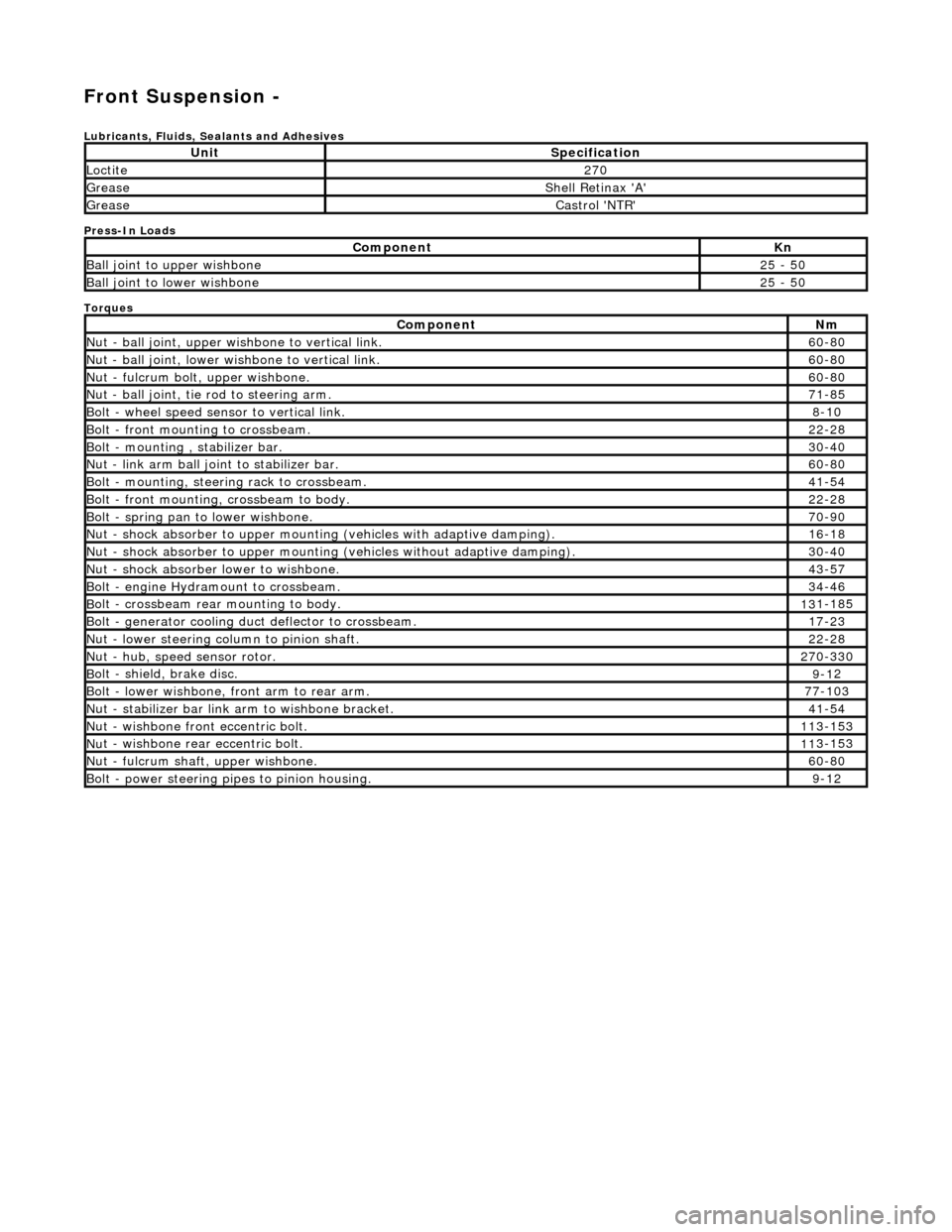
Front Suspension -
Lubri
cants, Fluids, Sealants and Adhesives
Press-In Loads
Torques
UnitS
pecification
Loctite27
0
Greas
e
Shell Retin
ax 'A'
Greas
e
Castro
l 'NTR'
Com
ponent
Kn
Ball join
t to upper wishbone
25
- 50
B
all joint to lower wishbone
25
- 50
Com
ponent
Nm
N
ut - ball joint, upper wishbone to vertical link.
60
-80
N
ut - ball joint, lower wishbone to vertical link.
60
-80
Nu
t - fulcrum bolt, upper wishbone.
60
-80
N
ut - ball joint, tie rod to steering arm.
71
-85
Bol
t - wheel speed sensor to vertical link.
8-1
0
Bol
t - front mounting to crossbeam.
22
-28
Bolt
- mounting , stabilizer bar.
30
-40
N
ut - link arm ball joint to stabilizer bar.
60
-80
Bolt
- mounting, steering rack to crossbeam.
41
-54
B
olt - front mounting, crossbeam to body.
22
-28
Bol
t - spring pan to lower wishbone.
70
-90
N
ut - shock absorber to upper mounting
(vehicles with adaptive damping).
16
-18
Nu
t - shock absorber to upper mounting (vehicles without adaptive damping).
30
-40
N
ut - shock absorber lower to wishbone.
43
-57
B
olt - engine Hydramount to crossbeam.
34
-46
B
olt - crossbeam rear mounting to body.
13
1-185
Bol
t - generator cooling du
ct deflector to crossbeam.
17
-23
N
ut - lower steering column to pinion shaft.
22
-28
N
ut - hub, speed sensor rotor.
27
0-330
B
olt - shield, brake disc.
9-1
2
Bol
t - lower wishbone, front arm to rear arm.
77
-103
Nu
t - stabilizer bar link arm to wishbone bracket.
41
-54
N
ut - wishbone front
eccentric bolt.
11
3-153
Nu
t - wishbone rear
eccentric bolt.
11
3-153
N
ut - fulcrum shaft, upper wishbone.
60
-80
Bolt -
power steering pi
pes to pinion housing.
9-1
2
Page 69 of 2490
Front C
rossbeam
A
fully stressed, pressed steel and tube fa
brication with integral lower wishbone tie bars, the crossbeam is secured to the
body on four resilient mountings.
The crossbeam incorporates mounting points for:
The u
pper and lower wish
bone fulcrum bolts.
The
stabilizer bar
The power steering rack. The engine h
ydramounts.
R
oad springs.
Slots and cam reaction pl ates on the crossbeam provide for ad justment of suspension geometry.
It
em
Par
t Number
De
scription
1—Cro
ssbeam
2—Upper
Wishbone
3—Lower Wi
shbone Arm, Front
4—Lower Wi
shbone Arm, Rear
5—Upper
Wishbone Ball Joint
6—Lower Wi
shbone Ball Joint
7—Ful
crum Bolt
8—Adjuster B
olt, Front
9—Adjuster B
olt, Rear
10—S
pring Pan
11—Shock Absorber Lower M
ounting Plate
12—Vertical Link
13—Hub Assembly
14—Sensor R
otor
15—B
olt, Wishbone to Link Arm
Page 72 of 2490
3. Lower front of vehicl
e.
4. W
A
RNING: ENSURE THAT THE DOWEL OF TOOL 204-114
IS CORRECTLY POSITIONED ACROSS THE SUSPENSION TURRET
SLOT.
Locate special tool in suspension turret slot.
Pas s
special tool 204-114 thro
ugh slot in suspension turret
and rotate stem to locate dowel.
5. WARNING: WHE N
TIGHTENING
TOOL NUT, USE LOWER
DOWEL AS A GUIDE TO ENSURE THAT THE TOOL STEM DOES
NOT ROTATE AND DISTURB POSITION OF DOWEL IN
SUSPENSION TURRET.
Tighten nut of special tool 204-114 to full extent, to achieve
suspension mid-laden position.
6. Ra
ise front of vehicle and support
on stands. refer to Section
100-02.
7. Remove appropriate road wheel. Refer to Section 100-02.
8. Remove an d discard tiestraps se
curing wheel speed sensor
harness to upper wishbone.
9. Move steering to appropriate full lock for access to suspension.
10 . R
emove nut securing upper wish
bone ball joint to vertical
link.
11. CAUTION: Do not use special tool 211-098 in the
Page 76 of 2490
5. Re
move wire temporarily securing
vertical link to road spring.
6. Remove and discard plasti c cover from ball joint.
7. Position wishb
o
ne to engage ball joint taper in vertical link.
8. In
stall nut securing ball joint to vertical link and tighten nut to
60-80Nm.
9. Reposition wheel speed sensor harness on wishbone and
secure with two tiestraps.
Page 80 of 2490
10. NOTE
: It is not necessary to re
move Special Tool from spring
at this stage.
Remove spring assembly and Special Tool 204-111 from
suspension turret.
11. Lower vehicle to working heig ht and support on stands.
12 . Remove an
d discard tiestraps
securing wheel speed sensor
harness to upper wishbone.
13 . R
emove wheel speed sensor se
curing screw and withdraw
sensor from vertical link.
14 . R
emove nut securing tie rod oute
r ball joint to steering arm.
15. Release tie rod ball joint from vertical link.
Page 88 of 2490

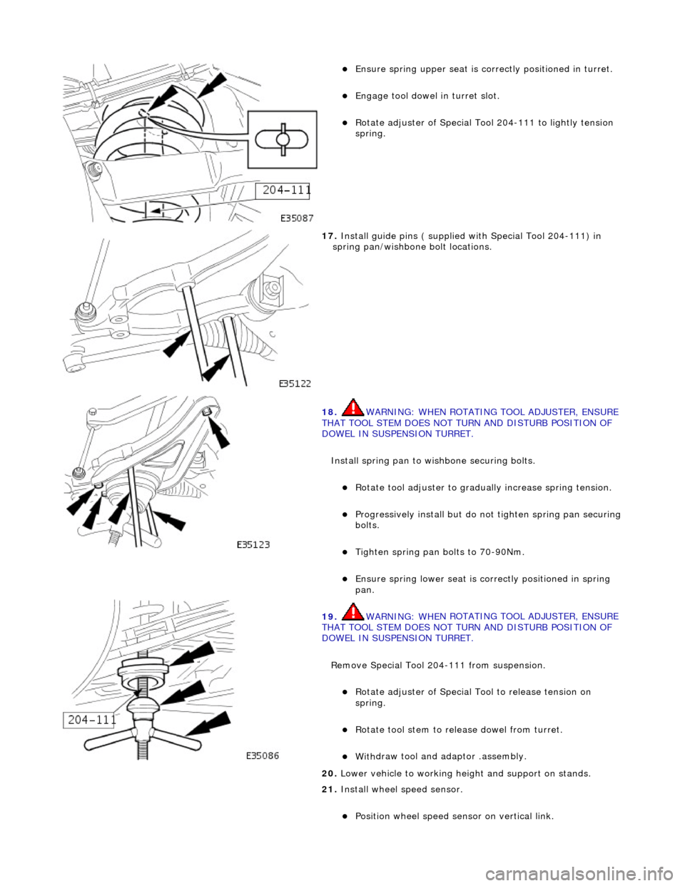
Ensure spring
upper se
at is correctly positioned in turret.
Engage tool dowel in turret slo
t.
R
o
tate adjuster of Special Tool 204-111 to lightly tension
spring.
17 . Ins
tall guide pins ( supplied with Special Tool 204-111) in
spring pan/wishbone bolt locations.
18 . WARNING: WHE
N ROTATING TOOL ADJUSTER, ENSURE
THAT TOOL STEM DOES NOT TU RN AND DISTURB POSITION OF
DOWEL IN SUSPENSION TURRET.
Install spring pan to wishbone securing bolts.
Ro t
ate tool adjuster to gradua
lly increase spring tension.
Pr
ogressively install but do no
t tighten spring pan securing
bolts.
Tigh ten spring pan
bolts to 70-90Nm.
Ensure spri
ng
lower seat is co
rrectly positioned in spring
pan.
19 . WARNING: WHE
N ROTATING TOOL ADJUSTER, ENSURE
THAT TOOL STEM DOES NOT TU RN AND DISTURB POSITION OF
DOWEL IN SUSPENSION TURRET.
Remove Special Tool 204-111 from suspension.
Rotat
e adjuster of Special Tool to release tension on
spring.
R otate
tool stem to release dowel from turret.
With
draw tool and adaptor
.assembly.
20
. Lower vehi
cle to working heig
ht and support on stands.
21. Install wheel speed sensor.
Positi
on wheel speed sensor on vertical link.
Page 89 of 2490
Inst
all sensor bolt an
d tighten to 8-10Nm.
22
.
Connect wheel speed sensor harness.
1. Connect wheel speed sensor harness to sensor.
2. Using new tiestraps secure wheel speed sensor harness to upper wishbone.
23
.
Install brake calipers.
R
emove tie supporting brake caliper.
1. Install caliper on carrier.
2. Install guide pins.
3. Install guide pin dust caps.
4. Install caliper spring clip.
24. Install road wheel. Re fer to Section 100-02.
25. Raise vehicle, remove stands and lower vehicle onto road
wheels.
26
.
Ensuring graduation mark remains aligned, finally tighten
wishbone rear eccentric bolt to 113-153Nm.
27. Check wheel alignment and if necessary adjust. Refer to
57.65.01.
Page 92 of 2490
10. NOTE
: It is not necessary to re
move Special Tool from spring
at this stage.
Remove spring assembly and Special Tool 204-111 from
suspension turret.
11. Lower vehicle to working heig ht and support on stands.
12 . Re
move tiestraps securing wheel speed sensor harness to
upper wishbone.
13 . R
emove wheel speed sensor se
curing screw and withdraw
sensor from vertical link.
14. Remove nut securing tie rod oute r ball joint to steering arm.