Page 2034 of 2490

Body Closures - Body Closures
Description and Operation
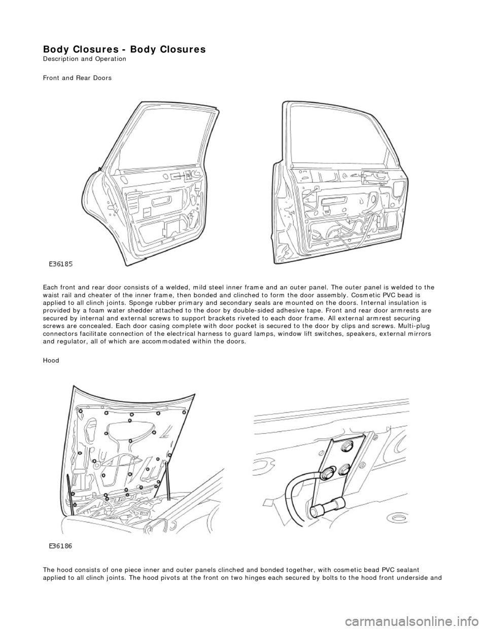
Front and Rear Doors
Each front and rear door consists of a welded, mild steel inner frame and an outer panel. The outer panel is welded to the
waist rail and cheater of the inner frame, then bonded and clinched to fo rm the door assembly. Cosmetic PVC bead is
applied to all clinch joints. Sponge rubber primary and secondary seals are mo unted on the doors. Internal insulation is
provided by a foam water shedder attached to the door by double-sided adhesive tape. Front and rear door armrests are
secured by internal and external screws to support brackets riveted to each door frame . All external armrest securing
screws are concealed. Each door casing complete with door po cket is secured to the door by clips and screws. Multi-plug
connectors facilitate connection of the electrical harness to guard lamps, window lift switches, speakers, external mirrors
and regulator, all of which are accommodated within the doors.
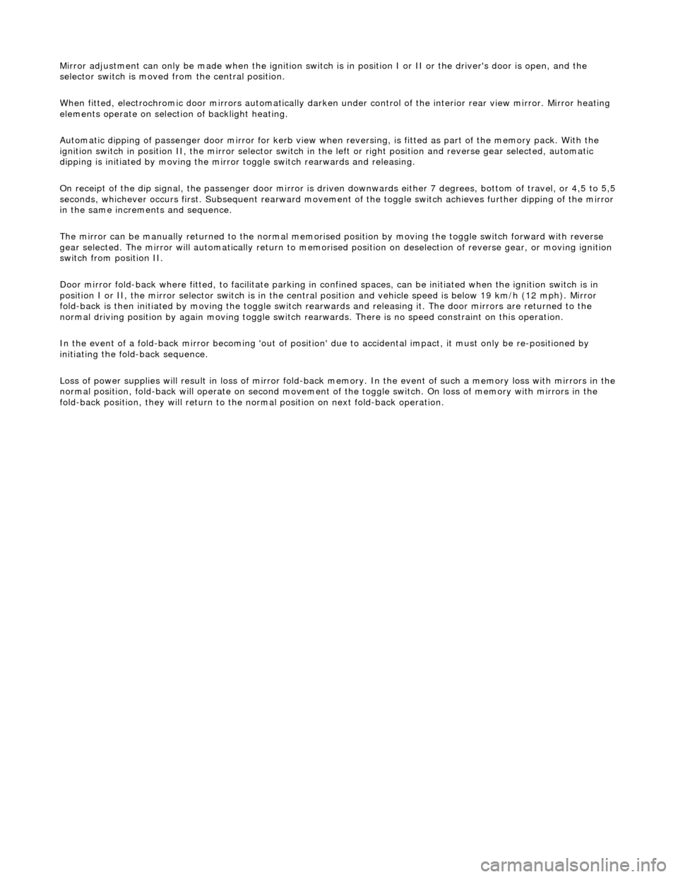
Hood
The hood consists of one piece inner an d outer panels clinched and bonded toge ther, with cosmetic bead PVC sealant
applied to all clinch joints. The hood pivo ts at the front on two hinges each secured by bolts to the hood front underside and
Page 2111 of 2490
Rear View Mirrors - Rear View Mirrors
Description and Operation
Interior Rear View Mirror
The interior rear view mirror is an elec trochromic unit that automatically darken s to prevent glare from following vehicle
lights. This automatic function is selected by pressing the switch at the bottom of the mirror. Pressing the switch again
cancels this function. An LE D then illuminates when automatic dipping is operative.
A Night Sentinel light sensing unit also incorporated in the mi rror casing, provides for automatic control of the vehicle lights.
Door Rear View Mirrors
The door mirrors are cheater mounted, colo r-keyed units, remote electrically adjustable and heated. Adjustment of both
mirrors is carried out from the driver's door switchpack. A slider switch selects the mirror to be adjusted, and a disc switch
adjusts the selected mirror to the required position.
Page 2112 of 2490

Mirror adjustment can only be made when the ignition switch is in position I or II or the driver's door is open, and the
selector switch is moved from the central position.
When fitted, electrochromic door mirrors au tomatically darken under control of the interior rear view mirror. Mirror heating
elements operate on selection of backlight heating.
Automatic dipping of passenger door mirror for kerb view when reversing, is fitted as part of the memory pack. With the
ignition switch in position II, the mirror selector switch in the left or right position and reverse gear selected, automatic
dipping is initiated by moving the mirro r toggle switch rearwards and releasing.
On receipt of the dip signal, th e passenger door mirror is driven downwards eith er 7 degrees, bottom of travel, or 4,5 to 5,5
seconds, whichever occurs first. Subsequent rear ward movement of the toggle switch achieves further dipping of the mirror
in the same increments and sequence.
The mirror can be manually returned to the normal memorised position by moving the toggle switch forward with reverse
gear selected. The mirror will automatically return to memorised position on deselection of reverse gear, or moving ignition
switch from position II.
Door mirror fold-back where fitted, to facilitate parking in conf ined spaces, can be initiated when the ignition switch is in
position I or II, the mirror selector switch is in the centra l position and vehicle speed is below 19 km/h (12 mph). Mirror
fold-back is then initiated by moving the toggle switch rear wards and releasing it. The door mirrors are returned to the
normal driving position by ag ain moving toggle switch rearwards. There is no speed constraint on this operation.
In the event of a fold-back mirror becoming 'out of position' du e to accidental impact, it must only be re-positioned by
initiating the fold-back sequence.
Loss of power supplies will result in loss of mirror fold-back memory. In the event of such a memory loss with mirrors in the
normal position, fold-back will operate on second movement of the toggle swit ch. On loss of memory with mirrors in the
fold-back position, they will return to the no rmal position on next fold-back operation.
Page 2113 of 2490
Rear View Mirrors - Auto-Dimming Interior Mirror
Removal and Installation
Removal
Installation
1.
Remove roof console for access and disconnect interior mirror
harness multiplugs. Refer to 76.13.69.90.
2. Remove upper cover from mirror stem.
3. Remove rain sensor unit. Refer to Section 501.16.
4. CAUTION: When removing mirror from base, care must
be exercised to ensure that base is not detached from windshield.
Applying firm downward pre ssure, remove mirror assembly
from base.
1. Position mirror at bottom of base and apply firm upward
pressure to fully seat and secure in position.
2. Install upper cover to mirror stem.
3. Position roof console at head er and connect mirror harness
multiplugs.
4. Install rain sensor unit. Refer to Section 501.16.
5. Install roof console. Refer to 76.13.69.
Page 2114 of 2490
Rear View Mirrors - Exterior Mirror
Removal and Installation
Removal
Installation
1.
Fully open door glass and ease top of door casing away from
door Refer to 76.34.01.
2. Remove door frame cheater trim and memory foam for access.
3. Remove mirror assembly from door.
1. Disconnect mirror harness multiplug.
2. Supporting mirror, slacken and remove securing screw and remove mirror assembly from door.
1. Fit exterior mirror assembly to door.
1. Pass harness and multiplu g through cheater aperture
and position mirror foot on cheater, locating the two
dowels correctly and ensuring correct seating on seal.
Fit and tighten the mirror assembly securing screw.
Connect mirror assembly harness multiplug, position in
door and reposition door foam.
2. Fit memory foam and door frame cheater trim.
3. Close door glass.
4. Fit top of door casing. Refer to 76.34.01.
Page 2115 of 2490
Rear View Mirrors - Exterior Mirror Cover
Removal and Installation
Removal
Installation
1.
Remove exterior mirror glass. Refer to 76.10.53.
2. Remove exterior mirror cap.
1. From housing interior, pr ess out the three cap dowels
complete with securing clips.
Remove mirror cap from casing.
Remove and discard the securing clips.
1. Fit cap to mirror housing.
1. Fit and fully seat new cap securing clips in mirror base.
2. Align mirror cap dowels with the securing clips and press firmly into place.
2. Fit mirror glass. Refer to 76.10.53.
Page 2116 of 2490

Rear View Mirrors - Exterior Mirror Glass
Removal and Installation
Removal
CAUTION: If as a result of accidental impact, a powered fold-back mirror is mo ved 'out of position', it must only be re-
positioned by initiating the fold-back sequence as described in this section. No attempt must be made to manually return
the mirror to the normal position. Failure to adopt this procedure will result in vibration of the unlocked mirror head and
consequent loss or distortion of rear vision.
Installation
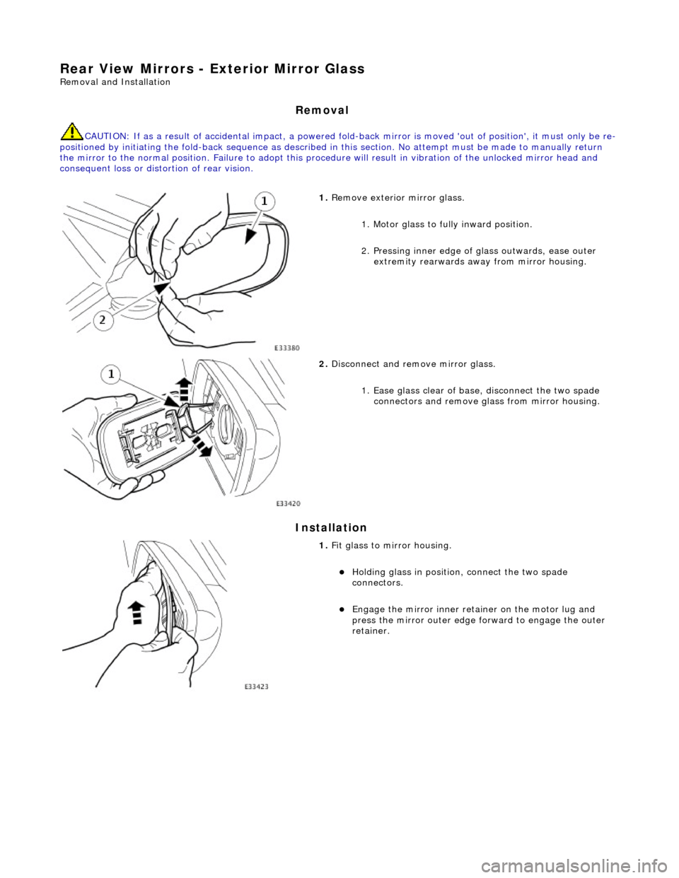
1. Remove exterior mirror glass.
1. Motor glass to fully inward position.
2. Pressing inner edge of glass outwards, ease outer
extremity rearwards away from mirror housing.
2. Disconnect and remove mirror glass.
1. Ease glass clear of base, disconnect the two spade connectors and remove gl ass from mirror housing.
1. Fit glass to mirror housing.
Holding glass in position , connect the two spade
connectors.
Engage the mirror inner retainer on the motor lug and
press the mirror outer edge fo rward to engage the outer
retainer.
Page 2117 of 2490
Rear View Mirrors - Exterior Mirror Motor
Removal and Installation
Removal
Installation
1.
Remove exterior mirror glass. Refer to 76.10.53.
2. Remove movement moto r pack from housing.
1. Slacken and remove the three self tapping screws
securing motor pack to housing.
2. Partially withdraw motor pack, disconnect multiplug and remove motor pack from mirror housing.
1. Fit glass movement motor pack to housing.
1. Connect multiplug and posi tion motor pack in housing
ensuring that harness is correctly routed and not
trapped.
2. Fit and tighten the three se lf tapping screws securing
motor pack to housing and fold-back mounting.
2. Fit exterior mirror glas s. Refer to 76.10.53.