Page 1866 of 2490
Information and Message Center - Information and Message Center
Diagnosis and Testing
Tests Using the Portable Diagnostic Unit
Refer to PDU User Guide
The complexity of the electronics involved with the speedomete r and instrument cluster, of which the Message Center is a
part, and the two multiplexed communication networks which ar e connected to it preclude the use of workshop general
electrical test equipment. Therefore, refe rence should be made to the PDU User Guide for detailed instructions on testing
the speedometer and odometer.
The PDU systematically te sts and analyses all functions and the various systems affected by it.
Where a fault is indicated, before replac ing a component, some basic diagnostic methods may be necessary to confirm that
connections are good and that wiring is not damaged.
Page 1977 of 2490

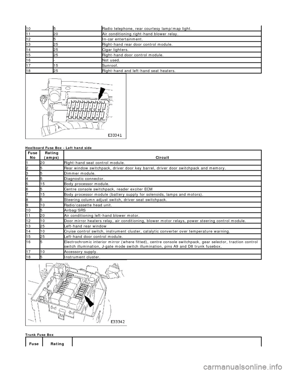
Heelboard Fuse Box - Left hand side
Trunk Fuse Box
105Radio telephone, rear courtesy lamp/map light.
1120Air conditioning right-hand blower relay.
125In-car entertainment.
1325Right-hand rear door control module.
1425Cigar lighters.
1525Right-hand door control module.
16-Not used.
1715Sunroof.
1825Right-hand and left-hand seat heaters.
Fuse NoRating
(amps)Circuit
120Right-hand seat control module.
25Rear window switchpack, driver door key ba rrel, driver door switchpack and memory.
35Dimmer module.
45Diagnostic connector.
515Body processor module.
65Centre console switchpack, reader exciter ECM
715Body processor module (battery supply for solenoids, lamps and motors).
85Steering column adjust switch, driver seat switchpack.
910Radio/cassette head unit.
105Airbag/SRS
1120Air conditioning left-hand blower motor.
1210Door mirror heaters relay, air conditioning, blow er motor relays, power steering control module.
1325Left-hand rear window
1410Cruise control switch, instrument cluster, catalytic converter over temperature warning.
1525Left-hand door control module.
165Electrochromic interior mirror (where fitted), centre console switchpack, gear selector, traction control
switch illumination, J-gate mode switch illumination, pins A9 and D8 trunk fusebox.
1710Accessory supply.
185Instrument cluster.
Fuse Rating
Page 2239 of 2490
Instrument Panel and Console - Instrument Cluster Finish Panel
Removal and Installation
Removal
Installation
1.
Turn ignition key to position II.
2. Move steering column to lowest and fully extended position.
3. Turn ignition key to position 'O'.
4. Remove battery cover and disc onnect ground cable from
battery terminal. Refer to 86.15.15.
5. Release veneer panel from retaining clips.
6. Remove veneer panel from vehicle.
7. Remove and discard all retaining clips.
1. Fit new retaining clips to instrument surround.
2. Fit and fully seat veneer pa nel to instrument surround.
3. Connect ground cable to battery terminal and fit battery cover.
Refer to 86.15.15.
4. Turn ignition key to position II.
5. Return steering column to original position.
6. Turn ignition key to position 'O'.
Page 2240 of 2490
Instrument Panel and Console - Instrument Cluster Finish Panel Bezel
Removal and Installation
Removal
1. Adjust steering column to full y extended and lowered position.
2. Remove battery cover and disc onnect ground cable from
battery terminal. Refer to 86.15.19.
3. Remove veneer from instrument panel. Refer to 76.47.24.
4. Using a small screwdriver, de press fog lamp switch upper
retaining tang and release sw itch from gauge surround.
5. Position fog lamp switch fo r access, disconnect harness
multiplug and remove switch.
6. Using a small screwdriver, depress trip keyboard upper
retaining tang and release ke yboard from gauge surround.
7. Position trip keyboard for ac cess and disconnect harness
multiplug.