Page 2099 of 2490
Exterior Trim and Ornamentation - Exterior Trim
Description and Operation
Body Front
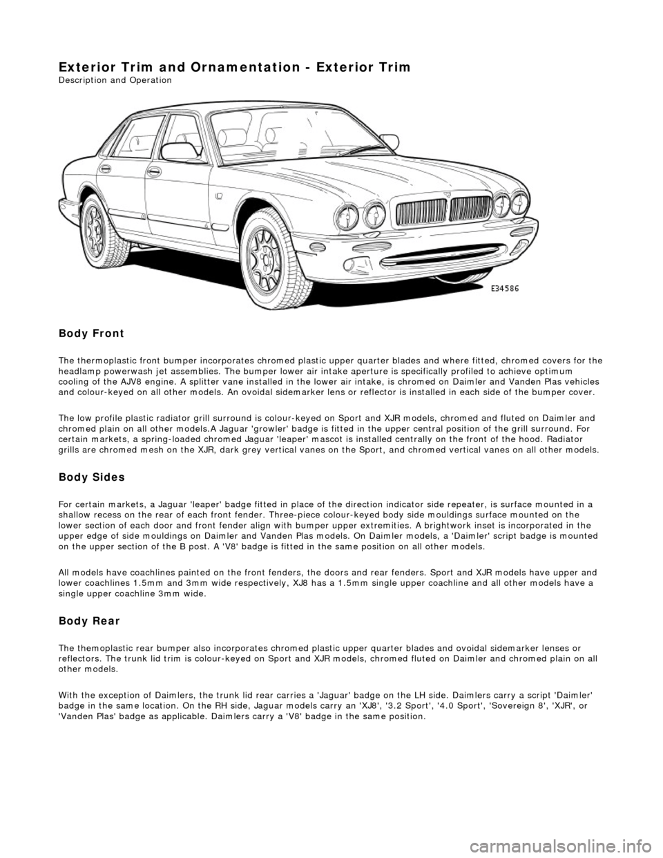
The thermoplastic front bumper incorporates chromed plastic upper quarter blades and where fitted, chromed covers for the headlamp powerwash jet assemblie s. The bumper lower air intake aperture is specifically profiled to achieve optimum
cooling of the AJV8 engine. A splitter vane installed in the lowe r air intake, is chromed on Daimler and Vanden Plas vehicles
and colour-keyed on all other models. An ov oidal sidemarker lens or reflector is installed in each side of the bumper cover.
The low profile plastic radiator grill surround is colour-keyed on Sport and XJR mo dels, chromed and fluted on Daimler and
chromed plain on all other models .A Jaguar 'growler' badge is fitted in the upper central positi on of the grill surround. For
certain markets, a spring-loaded chromed Ja guar 'leaper' mascot is installed centrally on the front of the hood. Radiator
grills are chromed mesh on the XJR, dark grey vertical vanes on the Sport, and chromed ve rtical vanes on all other models.
Body Sides
For certain markets, a Jaguar 'l eaper' badge fitted in place of the direction indicator side re peater, is surface mounted in a
shallow recess on the rear of each fro nt fender. Three-piece colour-keyed body side mouldings surface mounted on the
lower section of each door and front fender align with bumper upper extremities. A brightwork inset is incorporated in the
upper edge of side mouldings on Daimler and Vanden Plas models. On Daimler models, a 'Daimler' script badge is mounted
on the upper section of the B post. A 'V8' badge is fitted in the same position on all other models.
All models have coachlines painted on th e front fenders, the doors and rear fender s. Sport and XJR models have upper and
lower coachlines 1.5mm an d 3mm wide respectively, XJ8 has a 1.5mm single upper coachline and all other models have a
single upper coachline 3mm wide.
Body Rear
The themoplastic rear bumper also inco rporates chromed plastic upper quarter blades and ovoi dal sidemarker lenses or
reflectors. The trunk lid trim is colour-keyed on Sport and XJ R models, chromed fluted on Daimler and chromed plain on all
other models.
With the exception of Daimlers, the trunk lid rear carries a 'Jaguar' badge on the LH side. Daimlers carry a script 'Daimler'
badge in the same location. On th e RH side, Jaguar models carry an 'XJ8', '3.2 Sport', '4.0 Sport', 'Sovereign 8', 'XJR', or
'Vanden Plas' badge as applic able. Daimlers carry a 'V8' badge in the same position.
Page 2103 of 2490
Exterior Trim and Ornamentation - Door Moulding
Removal and Installation
Removal
Installation
1.
Apply suitable protecti ve tape to immediately adjacent areas of
paintwork.
2. Using a hand-held heat gun, appply heat uniformly along
moulding length.
3. Applying local heat at one end and using a suitable thin lever
to avoid damaging paintwork, progressively ease moulding
away from door panel.
4. Discard moulding and remove protective tape.
5. Remove any residual adhesive and thoroughly clean area using
white spirit.
1. NOTE: Optimum adhesion is achi eved by warming body panel
and moulding to 65deg C.
Using white spirit ensure that mounting area is clean, dry and
de-greased.
2. Remove protective backing tape from moulding.
3. NOTE: Do not allow moulding to contact the body panel until it
is correctly aligned.
Heat moulding and moun ting area to 65degC.)
4. Aligning with adjacent mouldings or to match opposite side of
vehicle, press new moulding firmly onto body panel.
5. Apply hand pressure along moulding length to ensure
satisfactory adhesion.
6. Allow moulding and door panel to cool , then thoroughly clean
both using white spirit.
7. Apply a coat of suitab le polish to moulding and body panel.
Page 2104 of 2490
Exterior Trim and Ornamentation - Front Fender Moulding
Removal and Installation
Removal
Installation
1.
Apply suitable protecti ve tape to immediately adjacent areas of
paintwork.
2. Using a hand-held heat gun, appply heat uniformly along
moulding length.
3. Applying local heat at one end and using a suitable thin lever
to avoid damaging paintwork, progressively ease moulding
away from fender.
4. Discard moulding and remove protective tape.
5. Remove any residual adhesive and thoroughly clean area using
white spirit.
1. NOTE: Optimum adhesion is achi eved by warming body panel
and moulding to 65deg C.
Using white spirit ensure that mounting area is clean, dry and
de-greased.
2. Remove protective backing tape from moulding.
3. NOTE: Do not allow moulding to contact the fender until it is
correctly aligned.
Heat moulding and mounting area to 65deg C.
4. Aligning with adjacent mouldings or to match opposite side of
vehicle, press new mouldi ng firmly onto fender.
5. Apply hand pressure along moulding length to ensure
satisfactory adhesion.
6. Allow moulding and fender to cool , then thoroughly clean both
using white spirit.
7. Apply a coat of suitable poli sh to moulding and fender.
Page 2179 of 2490
Glass, Frames and Mechanisms - Glass, Frames and Mechanisms
Description and Operation
Fixed Glass
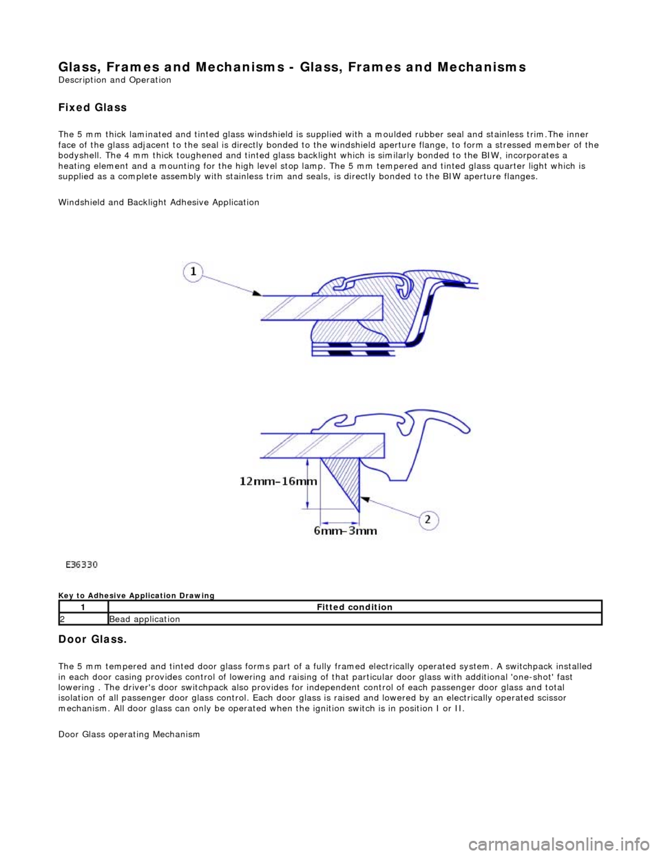
The 5 mm thick laminated and tinted glas s windshield is supplied with a moulded rubber seal and stainless trim.The inner
face of the glass adjacent to the seal is directly bonded to the windshield aperture flange, to form a stressed member of the
bodyshell. The 4 mm thick toughened and tinted glass backlight which is similarly bonded to the BIW, incorporates a
heating element and a mounting for the high level stop lamp. The 5 mm tempered and tinted glass quarter light which is
supplied as a complete assembly with stainless trim and seals, is directly bonded to the BIW aperture flanges.
Windshield and Backlight Adhesive Application
Key to Adhesive Application Drawing
Door Glass.
The 5 mm tempered and tinted door glass forms part of a fully framed electrically operated system. A switchpack installed
in each door casing provides control of lowering and raising of that particular d oor glass with additional 'one-shot' fast
lowering . The driver's door switchpack also provides for independent control of each passenger door glass and total
isolation of all passenger door glass control. Each door glas s is raised and lowered by an electrically operated scissor
mechanism. All door glass can only be operated wh en the ignition switch is in position I or II.
Door Glass operating Mechanism
1Fitted condition
2Bead application
Page 2200 of 2490
Glass, Frames and Mechanisms - Rear Quarter Window Glass
Removal and Installation
Removal
Special Tool(s)
Spray Bottle
WK9
Lubricant Concentrate
WK9L
Power Cutting Tool
WK10HD
Cutting Blade - Side
WK4ZS
Adhesive Removal Blade - Body
WK6
Betagun pneumatic application gun
Betagun 111
1. Remove the rear seat backrest.
For additional information, refer to: Rear Seat Backrest
(501-
10 Seating, Removal and Installation).
2. Remove both C-pill ar trim panels.
For additional information, refer to: C
-Pillar Trim Panel (501-05
Interior Trim and Ornamentatio n, Removal and Installation).
3. Place a suitable protective sheet over the parcel shelf and place
a protecting boar d over sheet.
4. Dispense 20ml of WK9L lubricant into the WK9 spray bottle, fill
Page 2201 of 2490
Installation
the spray bottle with water and mix.
5. Apply cutting lubricant to the rear quarter window glass
adhesive.
6. Install the cutting tool blade BTB-WK4ZS to the cutting tool
BTB-WK10HD.
7. WARNING: When removing the rear quarter window
glass, personal protec tion must be worn. Failure to follow this
instruction may result in personal injury.
• NOTE: Apply cutting lubricant to the cutting tool frequently
through out the cutting process.
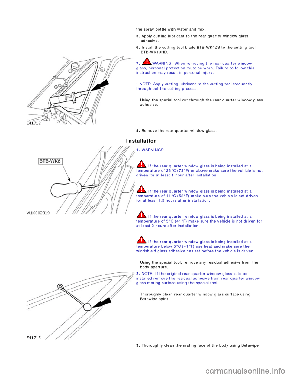
Using the special tool cut throug h the rear quarter window glass
adhesive.
8. Remove the rear quarter window glass.
1. WARNINGS:
If the rear quarter window glass is being installed at a
temperature of 23°C (73°F) or abov e make sure the vehicle is not
driven for at least 1 hour after installation.
If the rear quarter window glass is being installed at a
temperature of 11°C (52°F) make sure the vehicle is not driven
for at least 1.5 hours after installation.
If the rear quarter window glass is being installed at a
temperature of 5°C (41°F) make su re the vehicle is not driven for
at least 2 hours after installation.
If the rear quarter window glass is being installed at a
temperature below 5°C (41°F) use heat and make sure the
windshield glass adhesive has set before the vehicle is driven.
Using the special tool, remove any residual adhe sive from the
body aperture.
2. NOTE: If the original rear qu arter window glass is to be
installed remove the residual ad hesive from rear quarter window
glass mating surface using the special tool.
Thoroughly clean rear quarte r window glass surface using
Betawipe spirit.
3. Thoroughly clean the mating face of the body using Betawipe
Page 2202 of 2490
spirit.
4. Apply primer to the mating face of the glass.
5. Apply primer to the mating face of the body.
6. Cut the nozzle of the JLM20452 glass bonding adhesive to
achieve a triangular section bead 8 mm (0.32 in) wide by 10
mm (0.4 in) high.
7. Using the special tool, apply a uni form bead of adhesive to the
rear quarter window glass edge commencing at the bottom
center and overlapping the ends approximately 14 mm (0.56
in).
Page 2203 of 2490
8. CAUTIONS:
When installing the rear quarte r window glass, do not strike it in any way as this will crack the rear quarter window glass.
Make sure the rear quarter window glass does not move
out of position in the body aperture.
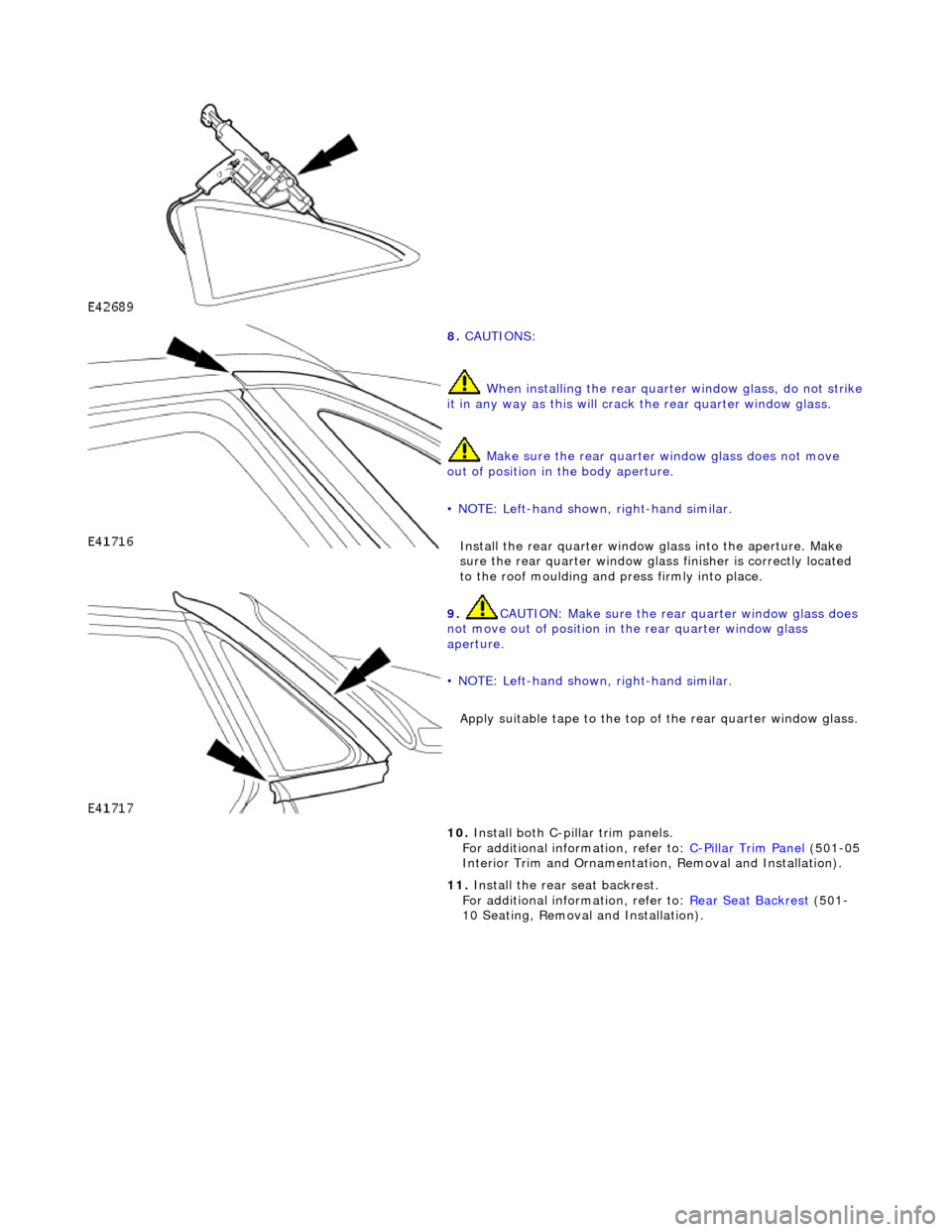
• NOTE: Left-hand shown, right-hand similar.
Install the rear quar ter window glass into the aperture. Make
sure the rear quarter window glas s finisher is correctly located
to the roof moulding and press firmly into place.
9. CAUTION: Make sure the rear quarter window glass does
not move out of position in the rear quarter window glass
aperture.
• NOTE: Left-hand shown, right-hand similar.
Apply suitable tape to the top of the rear quarter window glass.
10. Install both C-pillar trim panels.
For additional information, refer to: C-Pillar Trim Panel (501-05
Interior Trim and Ornamentatio n, Removal and Installation).
11. Install the rear seat backrest.
For additional information, refer to: Rear Seat Backrest
(501-
10 Seating, Removal and Installation).