Page 1248 of 2490
El
ectronic Engine Controls - En
gine Coolant Temperature (ECT)
Sensor4.0L SC V8 - AJ26
Re mo
val and Installation
Remova
l
Installation
1.
Op
en the engine compartment and fit paintwork protection
sheets.
2. WA
RNING: ENSURE THAT THE ENGINE IS COLD BEFORE
COMMENCING WORK.
Slacken the coolant reservoir ca p to relieve coolant pressure
and re-tighten.
3. Remove t
he engine coolant temperature sensor.
1. Disconnect the harness plug from the sensor.
2. Remove the sensor and sealing washer.
1. Fi
tting is the reverse of the removal procedure, noting that a
new sealing washer should be us ed and tighten the sensor as
specified
2. Check and adjust the cool ant level as required.
Page 1249 of 2490

Electron
ic Engine Controls -
Heated Oxygen Sensor (HO2S) LH
Rem
oval and Installation
General Equipment
Remov
al
Installation
Snap
-on tool S6176
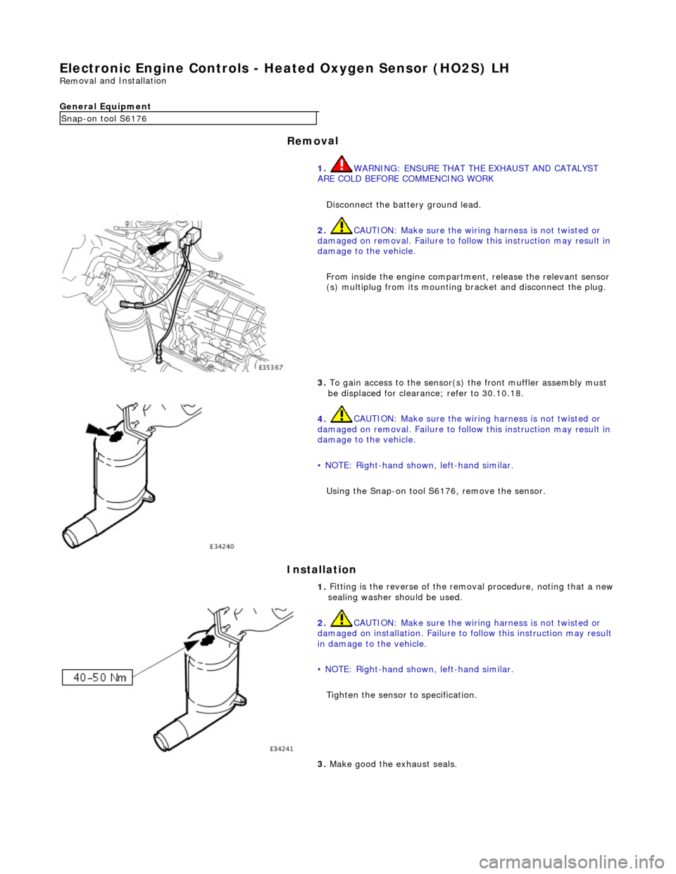
1. WARNING: ENSURE THAT TH E EXHAUST AND CATALYST
ARE COLD BEFORE COMMENCING WORK
Disconnect the battery ground lead.
2.
CAUTION: Make sure the wiring harness is not twisted or
damaged on removal. Failure to follow this instruction may result in
damage to the vehicle.
From inside the engine compartm ent, release the relevant sensor
(s) multiplug from its mounting bracket and disconnect the plug.
3.
To gain access to the sensor(s) the front muffler assembly must
be displaced for clearance; refer to 30.10.18.
4.
CAUTION: Make sure the wiring harness is not twisted or
damaged on removal. Failure to follow this instruction may result in
damage to the vehicle.
• NOTE: Right-hand shown, left-hand similar.
Using the Snap-on tool S6176, remove the sensor.
1.
Fitting is the reverse of the remo val procedure, noting that a new
sealing washer should be used.
2.
CAUTION: Make sure the wiring harness is not twisted or
damaged on installation. Failure to follow this instruction may result
in damage to the vehicle.
• NOTE: Right-hand shown, left-hand similar.
Tighten the sensor to specification.
3.
Make good the exhaust seals.
Page 1250 of 2490

Electronic
Engine Controls -
Heated Oxygen Sensor (HO2S) RH
Remo
val and Installation
General Equipment
Remov a
l
Installation
Snap -on to
ol S6176
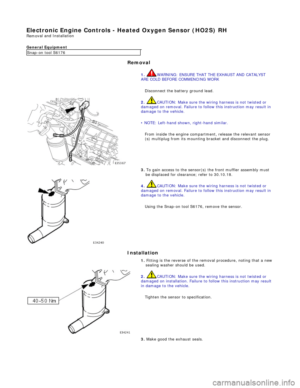
1. WARNING: ENSURE THAT TH E EXHAUST AND CATALYST
ARE COLD BEFORE COMMENCING WORK
Disconnect the battery ground lead.
2. CAU
TION: Make sure the wiring harness is not twisted or
damaged on removal. Failure to follow this instruction may result in
damage to the vehicle.
• NOTE: Left-hand shown, right-hand similar.
From inside the engine compartm ent, release the relevant sensor
(s) multiplug from its mounting bracket and disconnect the plug.
3. To
gain access to the sensor(s)
the front muffler assembly must
be displaced for clearance; refer to 30.10.18.
4. CAU
TION: Make sure the wiring harness is not twisted or
damaged on removal. Failure to follow this instruction may result in
damage to the vehicle.
Using the Snap-on tool S6176, remove the sensor.
1. Fittin
g is the reverse of the remo
val procedure, noting that a new
sealing washer should be used.
2. CAU
TION: Make sure the wiring harness is not twisted or
damaged on installation. Failure to follow this instruction may result
in damage to the vehicle.
Tighten the sensor to specification.
3. M
ake good the exhaust seals.
Page 1251 of 2490
E
lectronic Engine Controls - Inta
ke Air Temperature (IAT) Sensor
Re
moval and Installation
Remov
al
Installation
1.
Di
sconnect sensor connector at
rear of bank 1 charge air
cooler.
2. Re
move sensor.
Re
move sensor using a deep socket.
Discard sealin
g washer.
1. Installation is a reversal of the removal procedure.
Page 1252 of 2490
El
ectronic Engine Controls - Knock Se
nsor (KS) LH4.0L NA V8 - AJ27/3.2L
NA V8 - AJ26
Re mo
val and Installation
Remova
l
Installation
1.
Disc onne
ct battery ground cable (IMPORTANT, see SRO
86.15.19 for further information).
2. Remove for access, appropriat e engine cover; refer to
12.30.06.
3. NO TE
: Bank 1 shown.
Disconnect knock sensor conne ctor from mounting bracket.
4. Disc
onnect connector.
5. NO TE
: Bank 1 shown.
Using special tools, crowfoot and extension, remove knock
sensor.
1. Installation is a reversal of the removal procedure.
2. Tighten sensor to 31 - 41 Nm.
Page 1253 of 2490
E
lectronic Engine Controls - Knock
Sensor (KS) LH4.0L SC V8 - AJ26
Re
moval and Installation
Remov
al
Installation
1.
R
emove supercharger; refer to 18.50.15.
2. Remove knock sensor from engine.
De
tach connector and disconnect.
R
emove knock sensor.
1. Installation is a reversal of the removal procedure.
2. Tighten sensor to 31 - 41 Nm.
Page 1254 of 2490
El
ectronic Engine Controls - Knock Se
nsor (KS) RH4.0L NA V8 - AJ27/3.2L
NA V8 - AJ26
Re mo
val and Installation
Remova
l
Installation
1.
Disc onne
ct battery ground cable (IMPORTANT, see SRO
86.15.19 for further information).
2. Remove for access, appropriat e engine cover; refer to
12.30.06.
3. Disc onne
ct knock sensor conne
ctor from mounting bracket.
4. Disc
onnect connector.
5. Using speci a
l tools, crowfoot
and extension, remove knock
sensor.
1. Installation is a reversal of the removal procedure.
2. Tighten sensor to 31 - 41 Nm.
Page 1255 of 2490
E
lectronic Engine Controls - Knock
Sensor (KS) RH4.0L SC V8 - AJ26
Re
moval and Installation
Remov
al
Installation
1.
R
emove supercharger; refer to 18.50.15.
2. Remove knock sensor from engine.
De
tach connector and disconnect.
R
emove knock sensor.
1. Installation is a reversal of the removal procedure.
2. Tighten sensor to 31 - 41 Nm.