Page 1855 of 2490
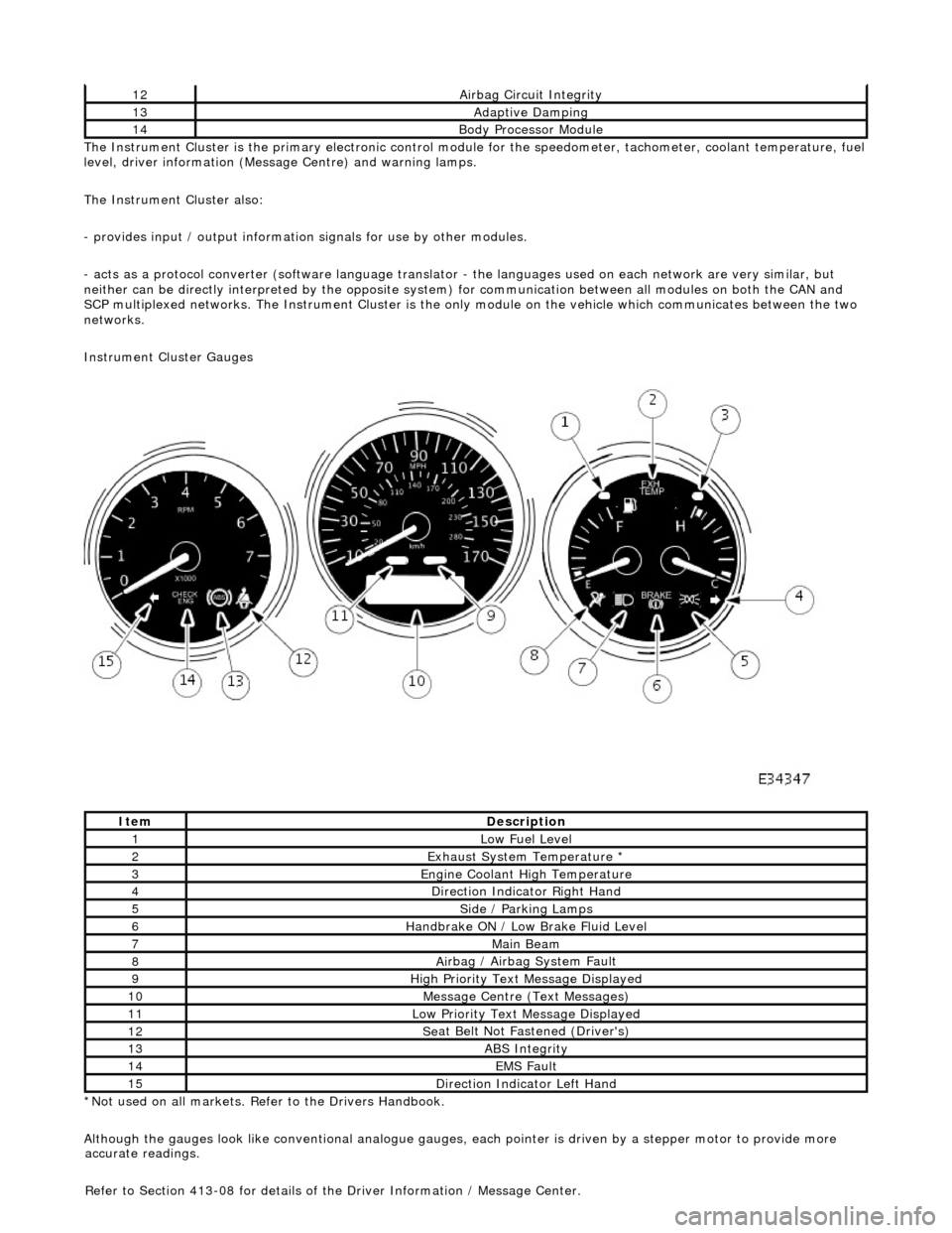
The In
strument Cluster is the primary electronic control module for the speedomete
r, tachometer, coolant temperature, fuel
level, driver information (Message Centre) and warning lamps.
The Instrument Cluster also:
- provides input / output informatio n signals for use by other modules.
- acts as a protocol converter (software language translator - the languages used on each network are very similar, but
neither can be directly interp reted by the opposite system) for communication between all modules on both the CAN and
SCP multiplexed networks. The Instrument Cluster is the only module on the vehicle which communicates between the two
networks.
Instrument Cluster Gauges
*Not used on all markets. Refer to the Drivers Handbook.
Although the gauges look like conventional analogue gauges, each pointer is driven by a stepper motor to provide more
12Ai
rbag Circuit Integrity
13Adaptive Damping
14Body Processor
Module
It
em
De
scription
1Low Fu
el Level
2Exhaus
t System Temperature *
3E
ngine Coolant High Temperature
4Di
rection Indicator Right Hand
5Side
/ Parking Lamps
6Handbrake ON / Low
Bra
ke Fluid Level
7Main
Beam
8Ai
rbag / Airbag System Fault
9Hi
gh Priority Text
Message Displayed
10M
essage Centre (Text Messages)
11Low Pri
ority Text Message Displayed
12Se
at Belt Not Fa
stened (Driver's)
13ABS Integrity
14EMS Fault
15D
irection Indicator Left Hand
accu
rate readings.
Refer to Section 413-08 for details of the Driver Information / Message Center.
Page 1859 of 2490
Horn - Horn
Description and Operation
The horns, located behind the radiator gril le, each side of the radiator, are controlled by the Body Processor Module (BPM),
as described below.
The switch, located on the steering wheel pad, is operated, it signals the BPM to sound the horn. The BPM responds by
providing an earth from the horn-output to the horn relay coil. The relay contacts are subsequently closed and the horns
sound.
The horn operating relay, R6 is located in the engine compartm ent fusebox at the left hand side of the engine compartment.
Page 1876 of 2490
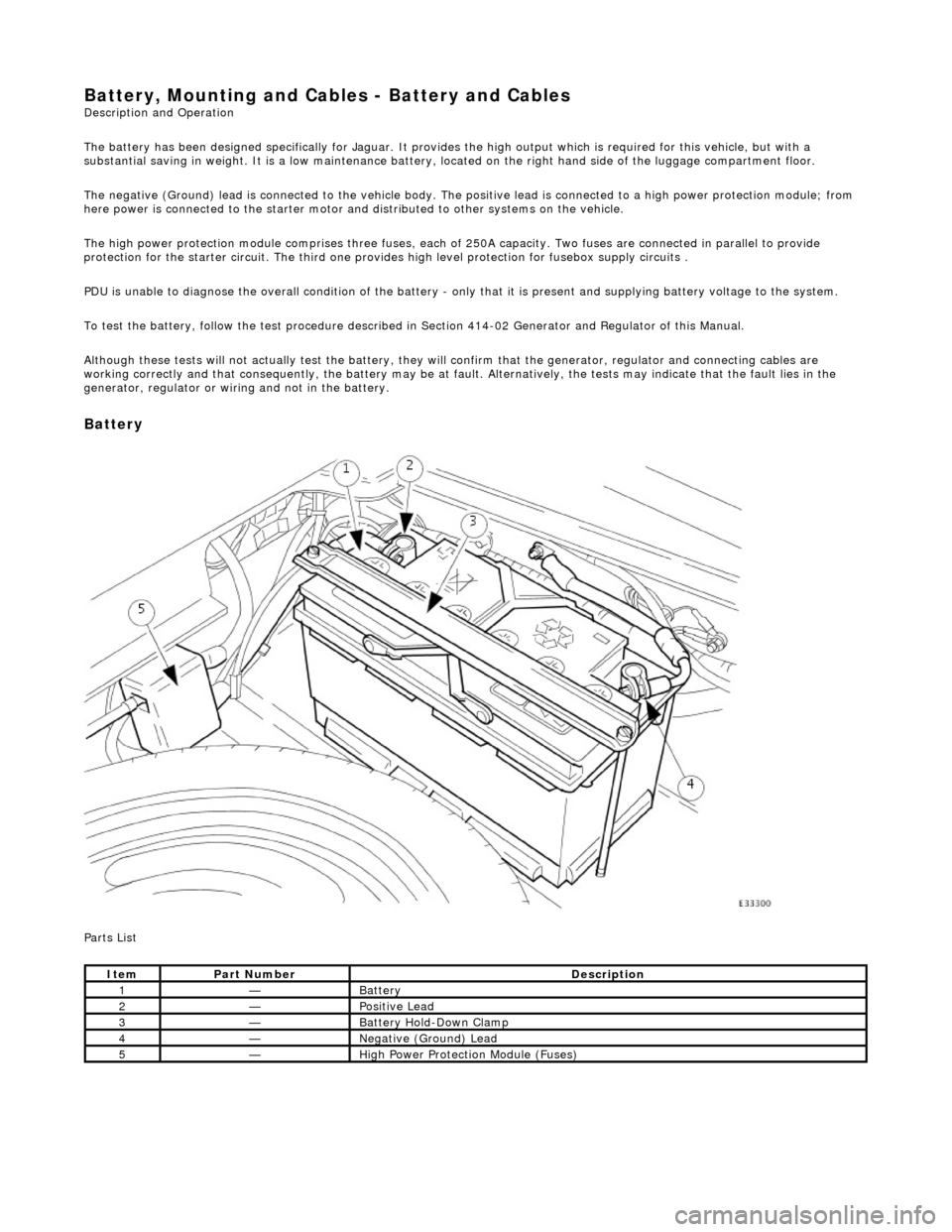
Battery, Mounting and Cables - Battery and Cables Description and Operation
The battery has been designed specifically for Jaguar. It provides the high output which is required for this vehicle, but with a
substantial saving in weight. It is a low maintenance battery, located on the right ha nd side of the luggage compartment floor.
The negative (Ground) lead is connected to the vehicle body. The positive lead is connected to a high power protection module; from
here power is connected to the starter motor an d distributed to other systems on the vehicle.
The high power protection module comprises three fuses, each of 250A capacity. Two fuses are connected in parallel to provide
protection for the starter circuit. Th e third one provides high level protection for fusebox supply circuits .
PDU is unable to diagnose the overall condition of the battery - only that it is present and supplying battery voltage to the system.
To test the battery, follow the test procedure described in Section 414-02 Generator and Regulator of this Manual.
Although these tests will not actually test the battery, they will confirm that the generator, regulator and connecting cables are
working correctly and that conseq uently, the battery may be at fault. Alternatively, the tests may indicate that the fault lies in the
generator, regulator or wiring and not in the battery.
Battery
Parts List
ItemPart NumberDescription
1—Battery
2—Positive Lead
3—Battery Hold-Down Clamp
4—Negative (Ground) Lead
5—High Power Protection Module (Fuses)
Page 1882 of 2490
Generator and Regulator - Generator
Description and Operation
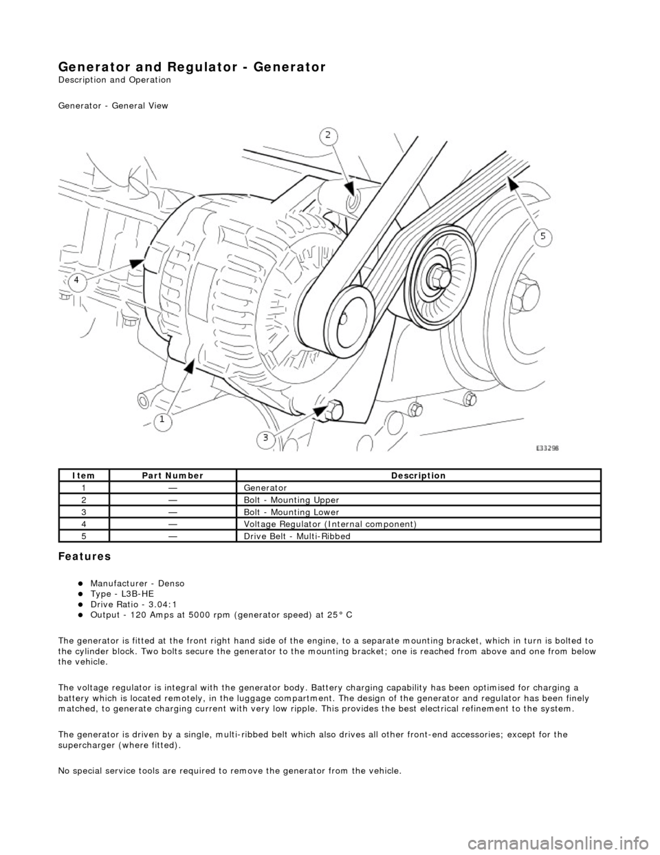
Generator - General View
Features
Manufacturer - Denso Type - L3B-HE Drive Ratio - 3.04:1 Output - 120 Amps at 5000 rpm (generator speed) at 25° C
The generator is fitted at the front right hand side of the engine, to a sepa rate mounting bracket, which in turn is bolted to
the cylinder block. Two bolts secure th e generator to the mounting bracket; one is reached from above and one from below
the vehicle.
The voltage regulator is integral with th e generator body. Battery charging capabi lity has been optimised for charging a
battery which is located remotely, in the luggage compartment. The design of the generator and regulator has been finely
matched, to generate charging current with very low ripple. This provides the best electrical refinement to the system.
The generator is driven by a single, multi-ribbed belt which also drives all other front-e nd accessories; except for the
supercharger (where fitted).
No special service tools are required to remove the generator from the vehicle.
ItemPart NumberDescription
1—Generator
2—Bolt - Mounting Upper
3—Bolt - Mounting Lower
4—Voltage Regulator (Internal component)
5—Drive Belt - Multi-Ribbed
Page 1883 of 2490
Belt tension is achieved by an automatic tensioner; neither the belt nor the tensioner require service apart from checking
the belt wear indicators at each normal service interval.
The minimum service life of the drive belt is 100,000 miles.
Never apply oil to the belt or to the belt tensioner.
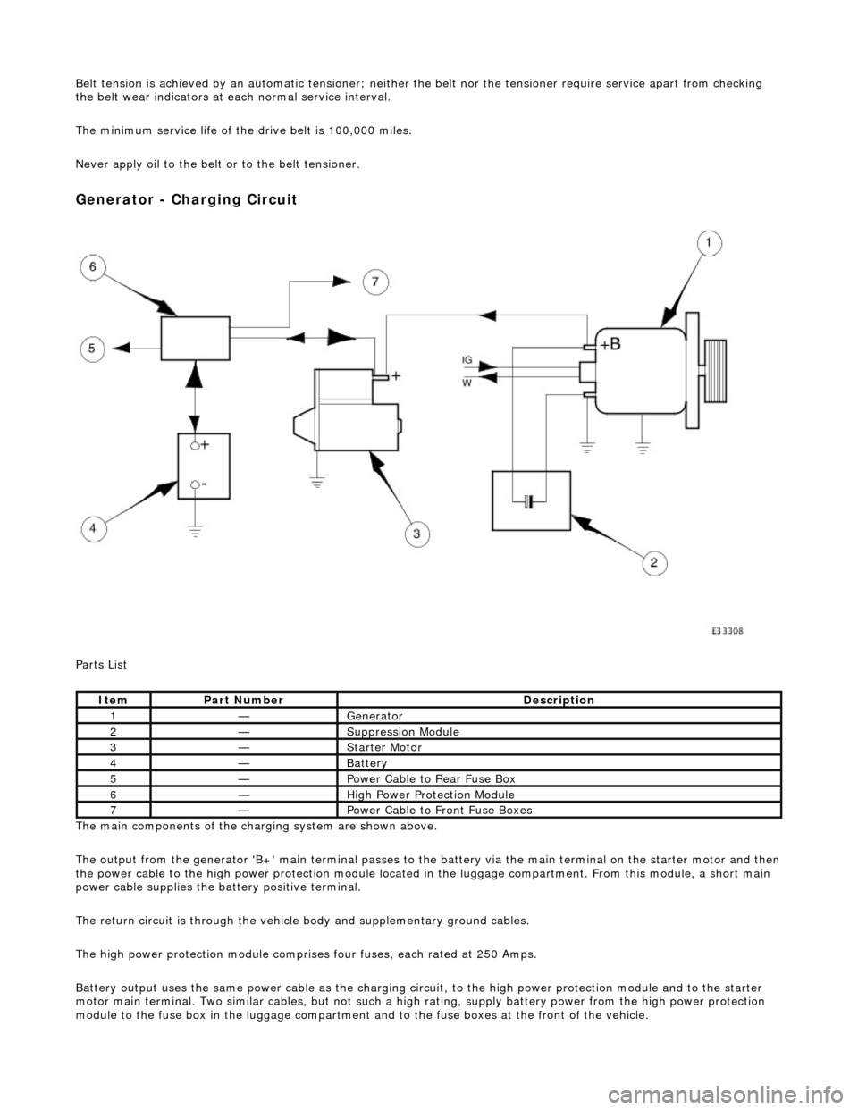
Generator - Charging Circuit
Parts List
The main components of the charging system are shown above.
The output from the generator 'B+' main te rminal passes to the battery via the main terminal on the starter motor and then
the power cable to the high power protection module located in the luggage compartment. From this module, a short main
power cable supplies the ba ttery positive terminal.
The return circuit is through the vehicle body and supplementary ground cables.
The high power protection mo dule comprises four fuses, each rated at 250 Amps.
Battery output uses the same power cable as the charging circ uit, to the high power protection module and to the starter
motor main terminal. Two similar cables, but not such a high rating, supply battery power from the high power protection
module to the fuse box in the luggage compartment an d to the fuse boxes at the front of the vehicle.
ItemPart NumberDescription
1—Generator
2—Suppression Module
3—Starter Motor
4—Battery
5—Power Cable to Rear Fuse Box
6—High Power Protection Module
7—Power Cable to Front Fuse Boxes
Page 1888 of 2490
detectable difference in the voltage reading (due to minimal current flow); if there is a detectable difference, clean the cable terminal and the adjacent area of the body.
When the voltage has been measured, STOP THE ENGINE.
Reconnect the battery or fit a new battery if it was established that the battery was at fault (Refer to 414-01).
If the cooling fans operate during the above test, the large demand of current will overload the generator and cause the
engine to stall.
If the battery is in a low state of charge the voltage will rise momentarily when the battery is disconnected. However, the
maximum that the voltage can increase to with this new gene rator is 25V and then only for a maximum time of 200 mS.
Using a Substitute Battery
A substitute battery may be fitted for the tests. This batter y must be a known good example and must have been off-charge for at least twelve hours, with a term inal voltage of approximately 12.8V.
Ensure that all electrical loads are swit ched OFF and that the engine is cool.
Start the engine and allow to IDLE.
Measure the voltage across the battery term inals. It should have dropped a little due to the large start current and then
risen to a value of between 13V and 15V.
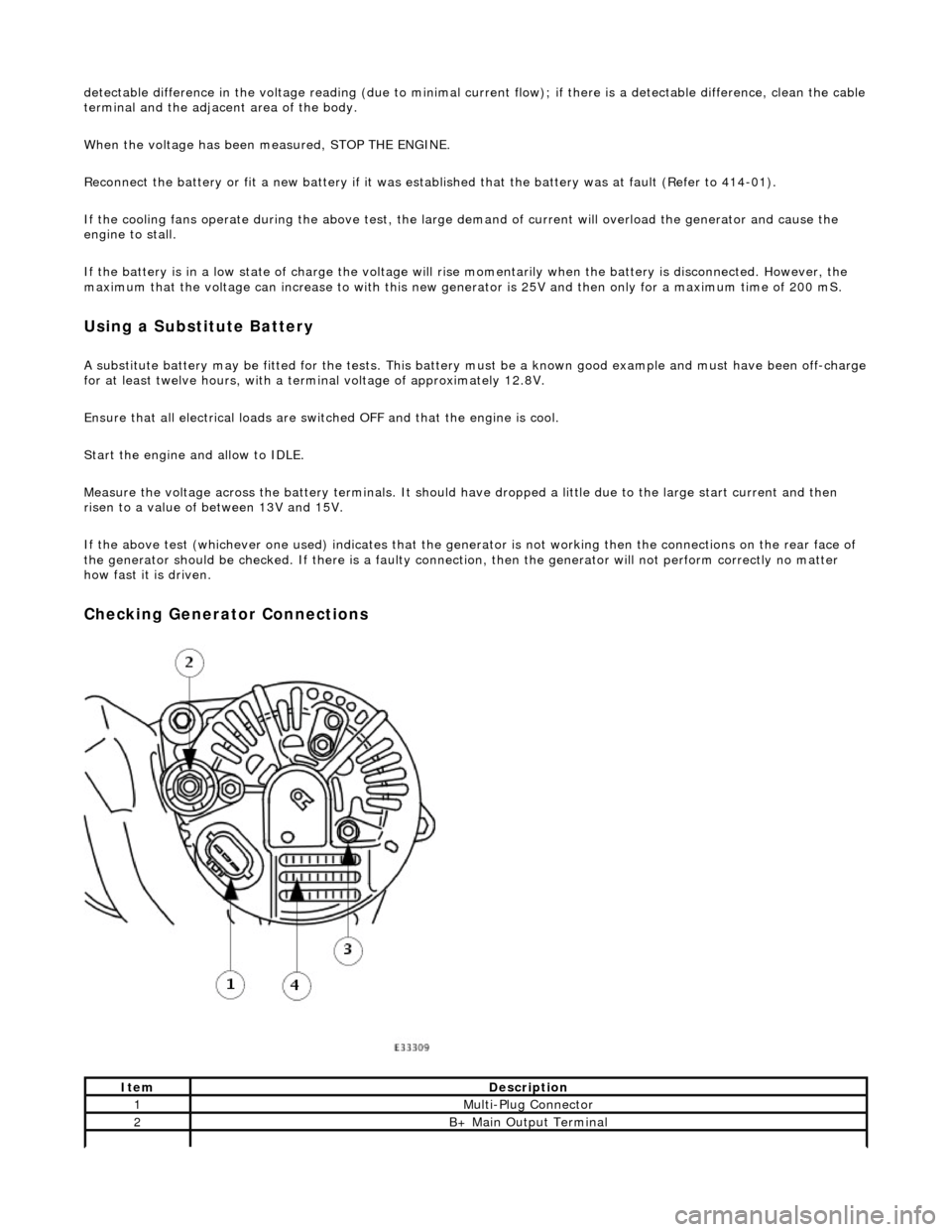
If the above test (whichever one used) indicates that the generator is not working then the connections on the rear face of
the generator should be checked. If there is a faulty connection, then the ge nerator will not perform correctly no matter
how fast it is driven.
Checking Generator Connections
ItemDescription
1Multi-Plug Connector
2B+ Main Output Terminal
Page 1890 of 2490
Generator and Regulator - Generator4.0L NA V8 - AJ27/3.2L NA V8 - AJ26
Removal and Installation
Removal
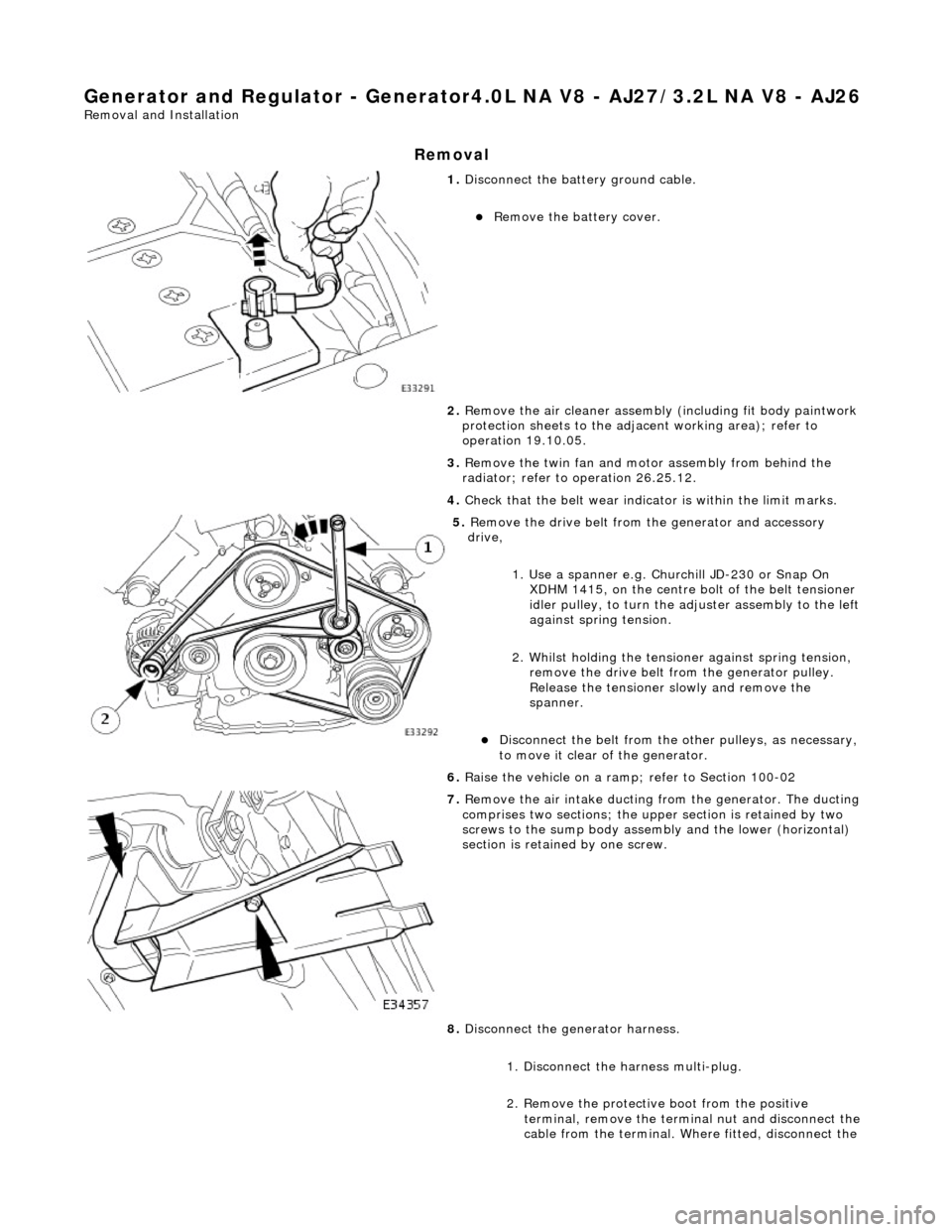
1. Disconnect the batt ery ground cable.
Remove the battery cover.
2. Remove the air cleaner assembly (including fit body paintwork
protection sheets to the adja cent working area); refer to
operation 19.10.05.
3. Remove the twin fan and moto r assembly from behind the
radiator; refer to operation 26.25.12.
4. Check that the belt wear indicator is within the limit marks.
5. Remove the drive belt from the generator and accessory
drive,
1. Use a spanner e.g. Churchill JD-230 or Snap On XDHM 1415, on the centre bo lt of the belt tensioner
idler pulley, to turn the adju ster assembly to the left
against spring tension.
2. Whilst holding the tensioner against spring tension, remove the drive belt from the generator pulley.
Release the tensioner sl owly and remove the
spanner.
Disconnect the belt from the ot her pulleys, as necessary,
to move it clear of the generator.
6. Raise the vehicle on a ramp; refer to Section 100-02
7. Remove the air intake ducting fr om the generator. The ducting
comprises two sections; the upper section is retained by two
screws to the sump body assembly and the lower (horizontal)
section is retained by one screw.
8. Disconnect the generator harness.
1. Disconnect the harness multi-plug.
2. Remove the protective boot from the positive
terminal, remove the termin al nut and disconnect the
cable from the terminal. Where fitted, disconnect the
Page 1893 of 2490
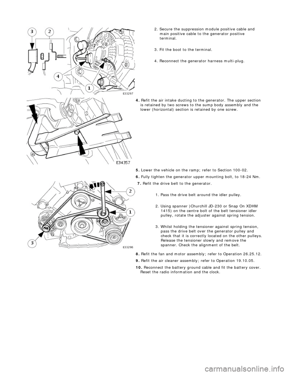
2. Secure the suppression module positive cable and
main positive cable to the generator positive
terminal.
3. Fit the boot to the terminal.
4. Reconnect the generator harness multi-plug.
4. Refit the air intake ducting to the generator. The upper section
is retained by two screws to the sump body assembly and the
lower (horizontal) section is retained by one screw.
5. Lower the vehicle on the ramp ; refer to Section 100-02.
6. Fully tighten the generator upper mounting bolt, to 18-24 Nm.
7. Refit the drive belt to the generator.
1. Pass the drive belt around the idler pulley.
2. Using spanner )Churchill JD-230 or Snap On XDHM 1415) on the centre bolt of the belt tensioner idler
pulley, rotate the adjuster against spring tension.
3. Whilst holding the tensioner against spring tension, pass the drive belt over the generator pulley and
check that it is correctly located on the other pulleys.
Release the tensioner slowly and remove the
spanner. Check the alignment of the belt.
8. Refit the fan and motor assembly ; refer to Operation 26.25.12.
9. Refit the air cleaner assembly; refer to Operation 19.10.05.
10. Reconnect the battery ground cable and fit the battery cover.
Reset the radio inform ation and the clock.