Page 1601 of 2490
With EM023 disconnected measure the insulation
resistance between sensor pin 001 and sensor body. 1
Repeat for pin 003 and sensor body. 2
Is the resistance > 10 MOHM?
Yes
GO to F11
No Renew the O2 sensor and reconnect plug(s).
GO to F10
F10: STOP
Perform appropriate service drive cycle and check for the
presence of DTC. 1
Has the fault code cleared?
Yes STOP
No Contact Jaguar Service
F11: SIGNAL GROUND 1 CONTINUITY
Page 1616 of 2490
With EM024 disconnected measure the insulation resistance
between sensor pin 001 and sensor body. 1
Repeat for pin 002 and sensor body. 2
Is the resistance > 10 MOHM?
Yes GO to G11
No Renew the O2 sensor and reconnect all plugs.
GO to G10
G10: STOP
Perform appropriate service drive cycle and check for the
presence of DTC. 1
Has the fault code cleared?
Yes STOP
No Contact Jaguar Service
G11: SIGNAL GROUND 1 CONTINUITY
Page 1629 of 2490
W
ith EM024 disconnected measur
e the insulation resistance
between sensor pin 001 and sensor body.
1
Repeat
for pin 002 and sensor body.
2
I
s the resistance > 10 MOHM?
Yes GO to H12
No Renew the O2 sensor and reconnect all plugs.
GO to H11
H1
1: STOP
Perform
appropriate service drive cycle and check for the
presence of DTC.
1
Has
the fault code cleared?
Yes STOP
No Contact Jaguar Service
H12: SI
GNAL GROUND 1 CONTINUITY
Page 1692 of 2490

Fuel Tank and Lines - Fuel Tank and Li
nes
Description an
d Operation
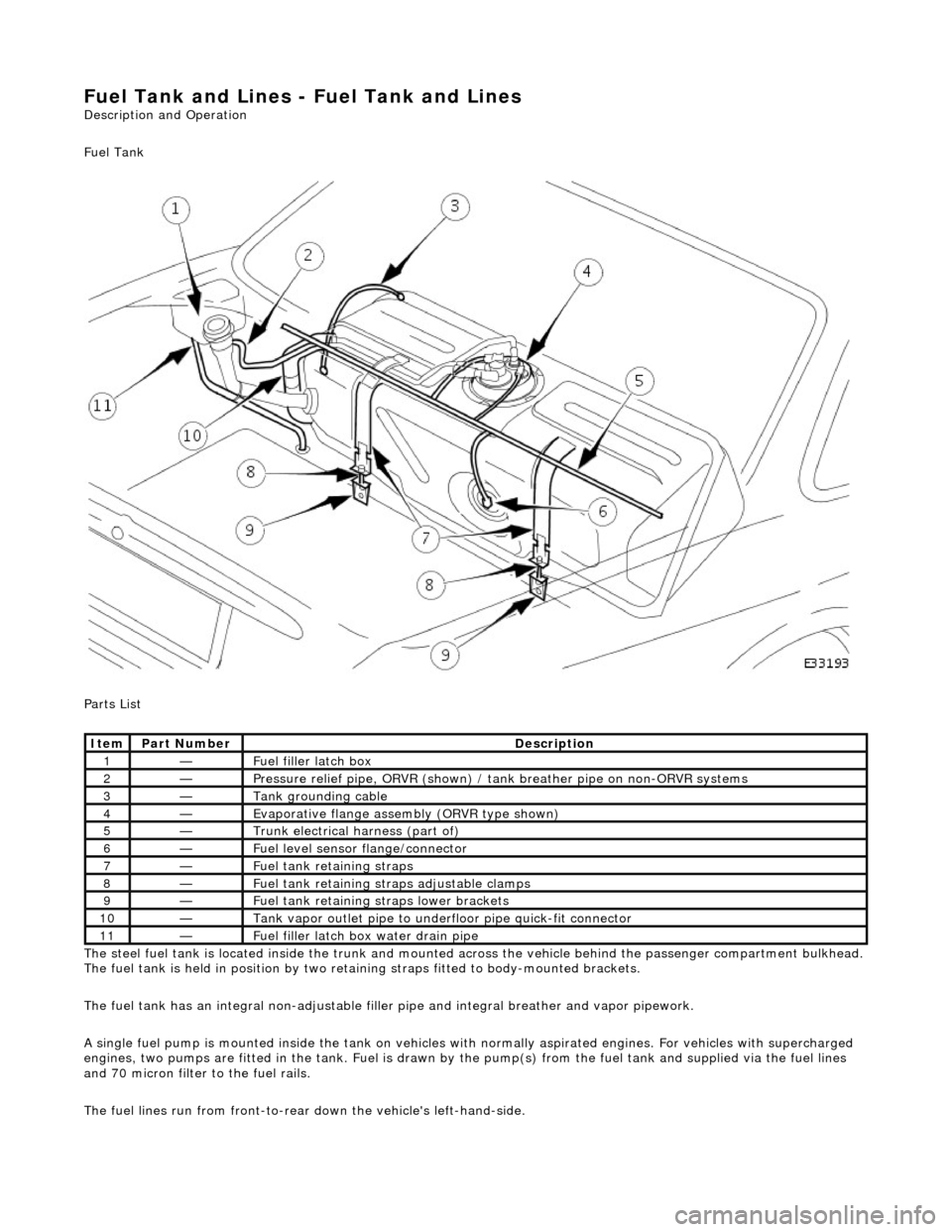
Fuel Tank
Parts List
The steel fuel tank is located inside the trunk and mounted across the vehicle behind the passenger compartment bulkhead.
The fuel tank is held in posi tion by two retaining straps fi tted to body-mounted brackets.
The fuel tank has an integral non-adjustable fill er pipe and integral breather and vapor pipework.
A single fuel pump is mounted inside the tank on vehicles with normally aspirated engines. For vehicles with supercharged
engines, two pumps are fitted in the tank. Fuel is drawn by the pump(s) from the fuel tank and supplied via the fuel lines
and 70 micron filter to the fuel rails.
The fuel lines run from front-to-rear down the vehicle's left-hand-side.
Ite
m
Part
Number
Descr
iption
1—Fu
el filler latch box
2—Pressure reli
ef pipe, ORVR
(shown) / tank breather pipe on non-ORVR systems
3—Tank grounding
cable
4—Evaporative flan
ge assembly
(ORVR type shown)
5—Trunk elec
trical harne
ss (part of)
6—Fue
l
level sensor
flange/connector
7—Fu
el tank retaining straps
8—F
u
el tank retaining stra
ps adjustable clamps
9—Fu
el tank retaining straps lower brackets
10—Tank vapor outlet pipe to un
derflo
or pipe quick-fit connector
11—F
u
el filler latch bo
x water drain pipe
Page 1736 of 2490

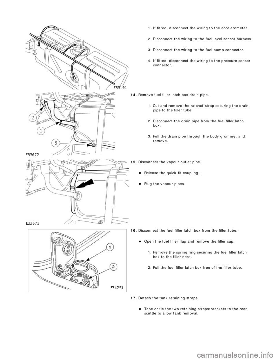
1.
If fitted, disconnect the
wiring to the accelerometer.
2. Disconnect the wiring to the fuel level sensor harness.
3.
Disc
onnect the wiring to
the fuel pump connector.
4. If fitted, disconnect the wi ring to the pressure sensor
connector.
14 . R
emove fuel filler
latch box drain pipe.
1. Cut and remove the ratche t strap securing the drain
pipe to the filler tube.
2. Disconnect the drain pipe from the fuel filler latch box.
3. Pull the drain pipe th rough the body grommet and
remove.
15 . Di
sconnect the vapo
ur outlet pipe.
Relea
se the quick-fit coupling .
Plu
g
the vapour pipes.
16 . D
isconnect the fuel filler la
tch box from the filler tube.
Open t
he fuel filler flap
and remove the filler cap.
1. Remove the spring ring se curing the fuel filler latch
box to the filler neck.
2. Pull the fuel filler latch box free of the filler tube.
17. Detach the tank retaining straps.
Tape or tie the two reta i
ning straps/brackets to the rear
scuttle to allow tank removal.
Page 1737 of 2490
I
nstallation
18
.
On non-ORVR vehicles, disconnect the trunk lid lefthand strut
rear pivot.
Pl
ace a suitable support under
trunk lid or tie to exterior
mirror.
1. Using a screwdriver, release clip at rear end of strut,
withdraw end from trunk lid pivot and lower strut.
19
.
Disconnect the tank ground cable from the vehicle body.
20. Remove the tank from the vehicle.
21. Drain any remaining fuel from the tank.
1. Fit the fuel tank assembly.
2. Re
-connect the tank ground cable to the vehicle.
Tigh
ten to 12 Nm.
3. On non-ORVR fuel tanks, positi on the trunk lid lefthand strut
between the filler tube and the breather pipe.
Page 1744 of 2490

Speed Control - Speed
Control
D
iagn
osis and Testing
Pri
n
ciples of operation
The s
p
eed (cruise) control sy
stem is activated by an ON/OFF master switch in the J-gate surround, which has an integral
LED to indicate status.
The steering wheel switches allow the driver to set the speed, increase or decrease the selected speed, cancel and resume
the facility without his/her hand ever leaving the steering wheel
The vehicle speed can be increased an d decreased in increments of 2 kmh (1 mph) by briefly pressing the + or - buttons up
to a maximum of five times.
Alternatively, the + or - button can be held until th e desired speed is reached.
The selected speed (by whichever method) w ill be displayed in the message center.
The system will not function at speeds below 26 kmh (16 mph), and can be cancelled from the master switch, the steering
wheel switches, and by depressing th e brake pedal. The system can be overridden by accelerating as normal.
In
spection and Verification
1.
1. Veri fy the customer concern.
2. 2. Vis
ually inspect for obvious signs of mechanical or electrical damage.
3. 3. If an obvious cause for an observed or reported concern is found, correct the cause (if possible) before proceeding
to the next step.
4. 4. If the cause is not visually evident, verify the symptom, check for DTCs and follow the routines in this section.
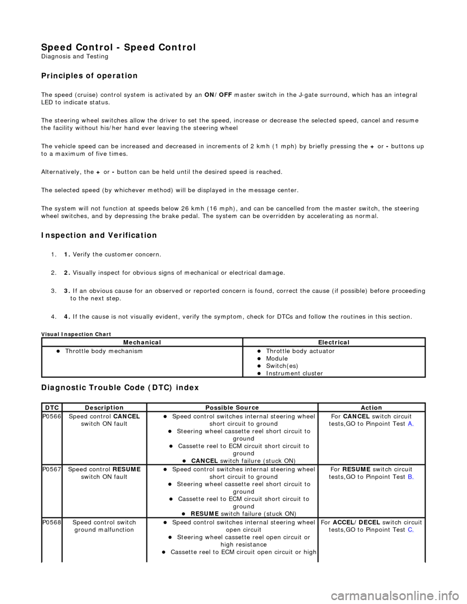
Vi
sual Inspection Chart
Diagnostic Trouble Code (D
TC) index
MechanicalElectrical
Throttle body mechan
ism
Throttle body actuator
Module Switch(es) Instrument cluster
DTC
De
scr
iption
Possib
l
e Source
Acti
o
n
P0566Speed
c
ontrol
CANCEL
switch ON fault
Speed
control switches internal steering wheel
short circuit to ground
St
eering wheel cassette reel short circuit to
ground
Cassette reel to ECM circ
uit short circuit to
ground
CANCEL
switch failure (stuck ON)
Fo
r
CANCEL switch circuit
tests,GO to Pinpoint Test A.
P0567Speed c
ontrol
RESUME
switch ON fault
Speed
control switches internal steering wheel
short circuit to ground
St
eering wheel cassette reel short circuit to
ground
Cassette reel to ECM circ
uit short circuit to
ground
RESUME swit
ch failure (stuck ON)
For
RESUME switch circuit
tests,GO to Pinpoint Test B.
P0568Spee
d control switch
ground malfunction
Speed
control switches internal steering wheel
open circuit
St
eering wheel cassette reel open circuit or
high resistance
Cassette reel to ECM ci
rcuit open circuit or high
For
ACCEL/DECEL switch circuit
tests,GO to Pinpoint Test C.
Page 1801 of 2490

Condenser:
Multi-pass fin-over-tube type, mounted in front of the engine cooling pack and directly to the radiator.
Pressure (Bitron) switch:
Located in the discharge pipe. Provides a signal, via the A/CCM, to th e ECM, to disengage the compressor clut ch should the refrigerant pressure be
< 2 bar or > 30 bar.
Provides a hard-wired signal to the ECM, to switch the cool ing fans to HIGH speed at 22 bar rising pressure and to
LOW speed at 17,5 bar falling pressure.
Provides a hard-wired signal to the ECM, to switch the radiator cooling fans to LOW speed at 12 bar rising pressure
and to switch the fans OFF at 8 bar falling pressure.
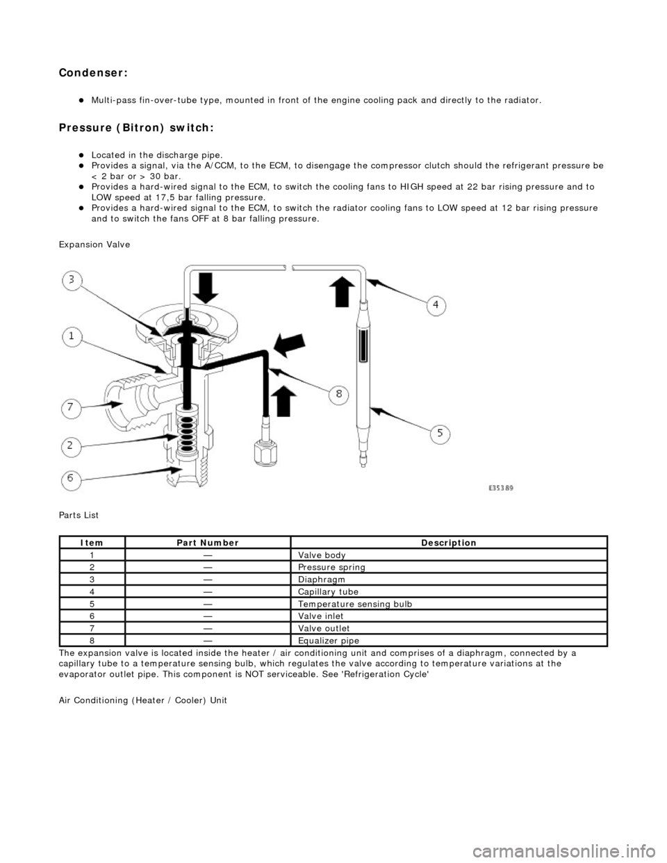
Expansion Valve
Parts List
The expansion valve is located inside the heater / air conditioning unit and comprises of a diaphragm, connected by a
capillary tube to a temperat ure sensing bulb, which regulates the valve according to temperature variations at the
evaporator outlet pipe. This component is NOT serviceable. See 'Refrigeration Cycle'
Air Conditioning (Heater / Cooler) Unit
ItemPart NumberDescription
1—Valve body
2—Pressure spring
3—Diaphragm
4—Capillary tube
5—Temperature sensing bulb
6—Valve inlet
7—Valve outlet
8—Equalizer pipe