1998 JAGUAR X308 body
[x] Cancel search: bodyPage 1207 of 2490
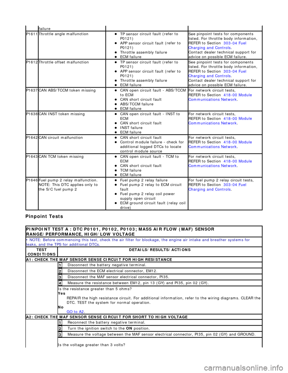
Pinpoint Tests
f
ailure
P1611Thr
ottle angle malfunction
TP sensor
circuit fault (refer to
P0121)
APP sensor circuit faul
t (refer to
P0121)
Throttl
e assembly failure
ECM failu
re
Se
e pinpoint tests for components
listed. For throttle body information,
REFER to Section 303
-04
Fuel
Charging and Con
trols
.
Contact deal
er technical support for
advice on possible ECM failure.
P1612Throttl
e offset malfunction
TP sensor
circuit fault (refer to
P0121)
APP sensor circuit faul
t (refer to
P0121)
Throttl
e assembly failure
ECM failu
re
Se
e pinpoint tests for components
listed. For throttle body information,
REFER to Section 303
-04
Fuel
Charging and Con
trols
.
Contact deal
er technical support for
advice on possible ECM failure.
P1637CAN AB
S/TCCM token missing
CAN
open circuit fault - ABS/TCCM
to ECM
CAN s
hort circuit fault
ABS/TCCM failu
re
ECM failu
re
F
or network circuit tests,
REFER to Section 418
-00
Module
Comm
unications Network
.
P1638CAN INST token missingCAN
open circuit fault - INST to
ECM
CAN s
hort circuit fault
INST
failure
ECM failu
re
F
or network circuit tests,
REFER to Section 418
-00
Module
Comm
unications Network
.
P1642CAN c
ircuit malfunction
CAN s
hort circuit fault
Control modul
e failure - check for
additional logged DTCs to locate
control module source
F
or network circuit tests,
REFER to Section 418
-00
Module
Comm
unications Network
.
P1643CAN TC
M token missing
CAN
open circuit fault - TCM to
ECM
CAN s
hort circuit fault
TCM failure
ECM failu
re
F
or network circuit tests,
REFER to Section 418
-00
Module
Comm
unications Network
.
P1646F
uel pump 2 relay malfunction.
NOTE: This DTC applies only to
the S/C fuel pump 2
F
uel pump 2 relay failure
F
uel pump 2 relay to ECM circuit
fault
F
uel pump 2 relay coil power
supply open circuit
ECM ground circuit faul
t (relay coil
drive)
F
or fuel pump 2 relay circuit tests,
REFER to Section 303
-04
Fuel
Charging and Con
trols
.
P
INPOINT TEST A : DTC P0101, P0102, P0103; MASS AIR FLOW (MAF) SENSOR
RANGE/PERFORMANCE, HIGH/LOW VOLTAGE
•
NOTE: Before commencing this
test, check the air filter for blockage, the engine air inta ke and breather systems for
leaks, and the TPS for additional DTCs.
TE
ST
CONDITIONS
D
ETAILS/RESULTS/ACTIONS
A1: CHECK
THE MAF SENSOR SENS
E CIRCUIT FOR HIGH RESISTANCE
Di
sconnect the battery negative terminal.
1
D
isconnect the ECM electrical connector, EM12.
2
Di
sconnect the MAF sensor electrical connector, PI35.
3
Meas
ure the resistance between EM12, pin 13 (GY) and PI35, pin 02 (GY).
4
Is th
e resistance greater than 5 ohms?
Yes REPAIR the high resistance circuit. For additional information, refer to the wiring diagrams. CLEAR the
DTC. TEST the system for normal operation.
No GO to A2
.
A2: CHECK
THE MAF SENSOR SENSE CI
RCUIT FOR SHORT TO HIGH VOLTAGE
R
econnect the battery negative terminal.
1
Turn the ignition swi
tch to the ON
position.
2
M
easure the voltage between the MAF sensor electrical connector, PI35, pin 02 (GY) and GROUND.
3
Is th
e voltage greater than 3 volts?
Page 1243 of 2490
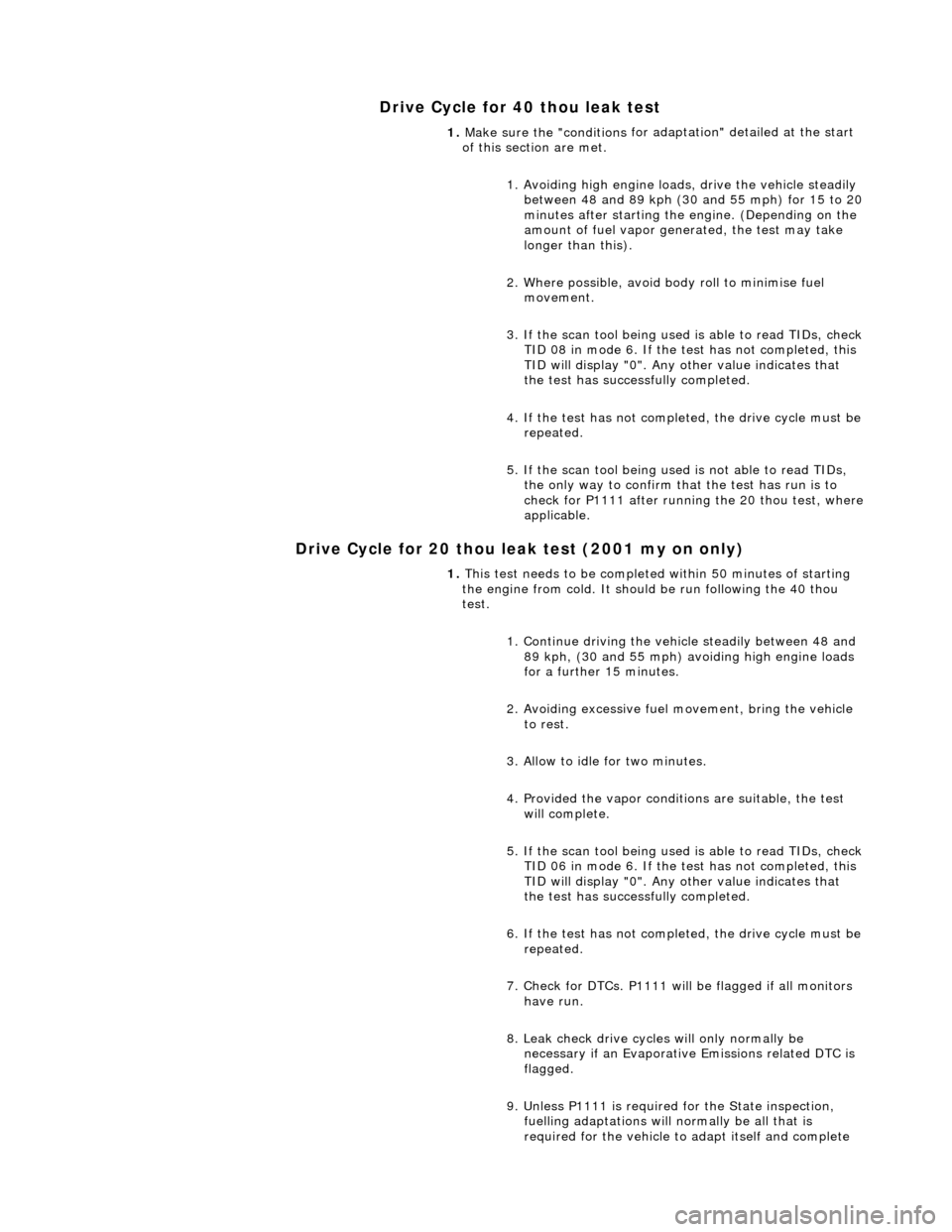
Drive Cycle for 40 thou leak test
Drive Cycle for 20 thou leak test (2001 my on only)
1. Make sure the "conditions
for ad
aptation" detailed at the start
of this section are met.
1. Avoiding high engine load s, drive the vehicle steadily
between 48 and 89 kph (30 and 55 mph) for 15 to 20
minutes after starting the engine. (Depending on the
amount of fuel vapor gene rated, the test may take
longer than this).
2. Where possible, avoid body roll to minimise fuel movement.
3. If the scan tool being used is able to read TIDs, check
TID 08 in mode 6. If the test has not completed, this
TID will display "0". Any other value indicates that
the test has successfully completed.
4. If the test has not completed, the drive cycle must be repeated.
5. If the scan tool being used is not able to read TIDs, the only way to confirm that the test has run is to
check for P1111 after running the 20 thou test, where
applicable.
1. This test needs to be completed within 50 minutes of starting
the engine from cold. It should be run following the 40 thou
test.
1. Continue driving the vehi cle steadily between 48 and
89 kph, (30 and 55 mph) avoiding high engine loads
for a further 15 minutes.
2. Avoiding excessive fuel movement, bring the vehicle to rest.
3. Allow to idle for two minutes.
4. Provided the vapor conditions are suitable, the test will complete.
5. If the scan tool being used is able to read TIDs, check
TID 06 in mode 6. If the test has not completed, this
TID will display "0". Any other value indicates that
the test has successfully completed.
6. If the test has not completed, the drive cycle must be repeated.
7. Check for DTCs. P1111 will be flagged if all monitors have run.
8. Leak check drive cycles will only normally be necessary if an Evaporative Emissions related DTC is
flagged.
9. Unless P1111 is required for the State inspection, fuelling adaptations will normally be all that is
required for the vehicle to adapt itself and complete
Page 1260 of 2490
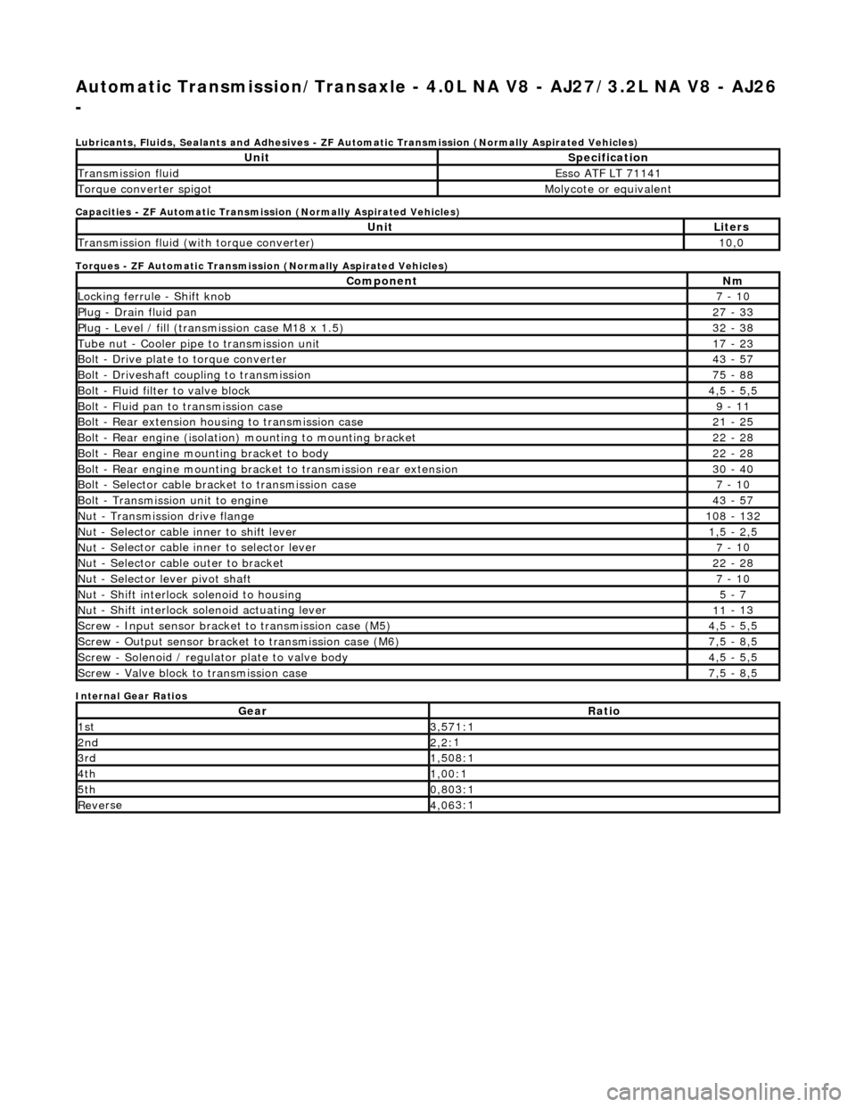
Automatic Transmission/Transaxle - 4.0L NA V8 - AJ27/3.2L NA V8 - AJ26
-
Lubri c
ants, Fluids, Sealants and Adhesives - ZF Au
tomatic Transmission (Normally Aspirated Vehicles)
Capacities - ZF Automatic Transmission (Normally Aspirated Vehicles)
Torques - ZF Automatic Transmission (Normally Aspirated Vehicles)
Internal Gear Ratios
UnitS p
ecification
Transmissi
on fluidEsso
ATF LT 71141
Torque converter spigotMolyc
o
te or equivalent
UnitLi
t
ers
Transmissi
on fluid (with
torque converter)
10
,0
Com p
onent
Nm
Locki
n
g ferrule - Shift knob
7 -
10
P
l
ug - Drain fluid pan
27
-
33
P
l
ug - Level / fill (transmission case M18 x 1.5)
32
-
38
Tu
be
nut - Cooler pipe to transmission unit
17
-
23
B
o
lt - Drive plate to torque converter
43
-
57
B
o
lt - Driveshaft coupling to transmission
75
-
88
Bo
lt
- Fluid filter to valve block
4,
5 -
5,5
Bolt
-
Fluid pan to transmission case
9 -
11
B
o
lt - Rear extension housing to transmission case
21
-
25
Bolt
-
Rear engine (isolation) mounting to mounting bracket
22
-
28
Bolt -
Rear engine moun
ting bracket to body
22
-
28
Bolt
-
Rear engine mounting bracke
t to transmission rear extension
30 -
40
B
o
lt - Selector cable bracket to transmission case
7 -
10
Bolt
-
Transmission unit to engine
43
-
57
Nu
t -
Transmission drive flange
1
08 -
132
Nu
t -
Selector cable inner to shift lever
1,
5 -
2,5
Nu
t -
Selector cable inner to selector lever
7 -
10
Nu
t -
Selector cable outer to bracket
22
-
28
Nu
t
- Selector lever pivot shaft
7 -
10
Nu
t -
Shift interlock solenoid to housing
5 -
7
Nut -
Shift interlock solenoid actuating lever
11
-
13
Sc
re
w - Input sensor bracket to transmission case (M5)
4,
5 -
5,5
Screw
-
Output sensor bracket to transmission case (M6)
7,
5 -
8,5
Screw
-
Solenoid / regulator plate to valve body
4,
5 -
5,5
Sc
re
w - Valve block to transmission case
7,
5 -
8,5
GearRatio
1s
t3,57
1:1
2n
d2,2:
1
3r
d1,50
8:1
4t
h1,00
:1
5t
h0,80
3:1
Re
ve
rse
4,
06
3:1
Page 1270 of 2490
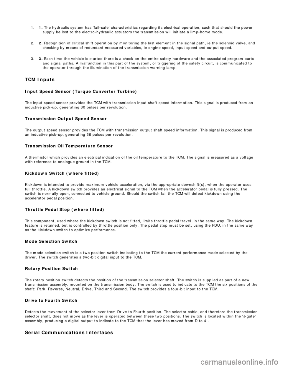
1.1. The hydraulic system has 'fail-safe' characteristics regardin g its electrical operation, such that should the power
supply be lost to the electro-hydraulic actuators the transmission will initiate a limp-home mode.
2. 2. Recognition of critical shift operation by monitoring the last element in the signal path, ie the solenoid valve, and
checking by means of redundant me asured variables, ie engine speed, input speed and output speed.
3. 3. Each time the vehicle is started there is a check on the entire safety hardware and the associated program parts
and signal paths. A malfunction in this part of the system, or triggering of the safety circuit, is communicated to
the operator through the illumination of the transmission warning lamp.
TCM Inputs
Input Speed Sensor (Torque Converter Turbine)
The input speed sensor provides the TCM with transmission inpu t shaft speed information. This signal is produced from an
inductive pick-up, generating 30 pulses per revolution.
Transmission Output Speed Sensor
The output speed sensor provides the TCM with transmission ou tput shaft speed information. This signal is produced from
an inductive pick-up, generati ng 36 pulses per revolution.
Transmission Oil Temperature Sensor
A thermistor which provides an electrical indication of the oi l temperature to the TCM. The signal is measured as a voltage
with reference to analog ue ground in the TCM.
Kickdown Switch (where fitted)
Kickdown is intended to provide maximum vehicle acceleration , via the appropriate downshift(s), when the operator uses
full throttle. A kickdown switch provides an electrical signal to the TCM wh en the accelerator pedal is fully pressed. The
switch is normally open, connected to vehicle ground. Should the switch fail the TCM will detect kickdown using the
accelerator pedal position.
Throttle Pedal Stop (where fitted)
This component, used where the kickdown switch is not fitted, limits throttle pedal travel .in the same way. The kickdown
feature is retained, but is controlled by throttle position only. The pedal stop must be set, using the PDU, in the same way
as the kickdown switch to optimize performance.
Mode Selection Switch
The mode selection switch is a two position switch indicati ng to the TCM the current performance mode selected by the
driver. The switch generates a tw o-bit digital input to the TCM.
Rotary Position Switch
The rotary position switch detects the position of the transmis sion selector shaft. The switch is supplied as part of a new
transmission assembly, mounted on the transmission body. The swit ch is used to indicate to the TCM the six positions of the shaft: Park, Reverse, Neutral, Drive, Third and Second. The switch provides a four-bit input to the TCM.
Drive to Fourth Switch
Detects the movement of the selector lever from Drive to Fourth position. The selector cable, and therefore the transmission selector shaft, does not move as the lever is operated between these two positions. The switch is located within the 'J-gate'
assembly, producing a digital output to indicate to the TCM that the lever has moved from D to 4 .
Serial Communications Interfaces
Page 1339 of 2490
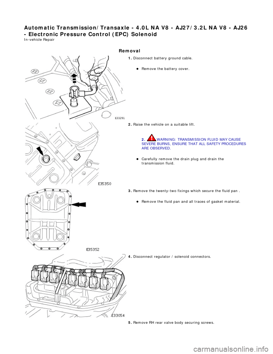
Automatic Transmission/Transaxle - 4.0L NA V8 - AJ27/3.2L NA V8 - AJ26
- Electronic Pressure Control (EPC) Solenoid
In-vehicle Repair
Removal
1. Disconnect battery ground cable.
Remove the battery cover.
2. Raise the vehicle on a suitable lift.
2. WARNING: TRANSMISSION FLUID MAY CAUSE
SEVERE BURNS, ENSURE THAT ALL SAFETY PROCEDURES
ARE OBSERVED.
Carefully remove the drain plug and drain the
transmission fluid.
3. Remove the twenty-two fixings which secure the fluid pan .
Remove the fluid pan and all traces of gasket material.
4. Disconnect regulator / solenoid connectors.
5. Remove RH rear valve body securing screws.
Page 1340 of 2490
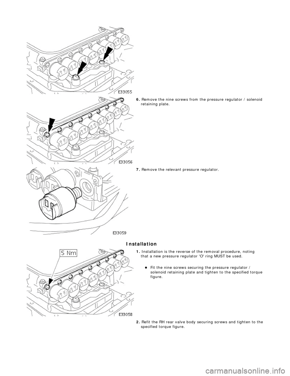
Installation
6. Remove the nine screws from th e pressure regulator / solenoid
retaining plate.
7. Remove the relevant pressure regulator.
1. Installation is the reverse of the removal procedure, noting
that a new pressure regulator 'O' ring MUST be used.
Fit the nine screws securing the pressure regulator /
solenoid retaining plate and ti ghten to the specified torque
figure.
2. Refit the RH rear valve body secu ring screws and tighten to the
specified torque figure.
Page 1345 of 2490
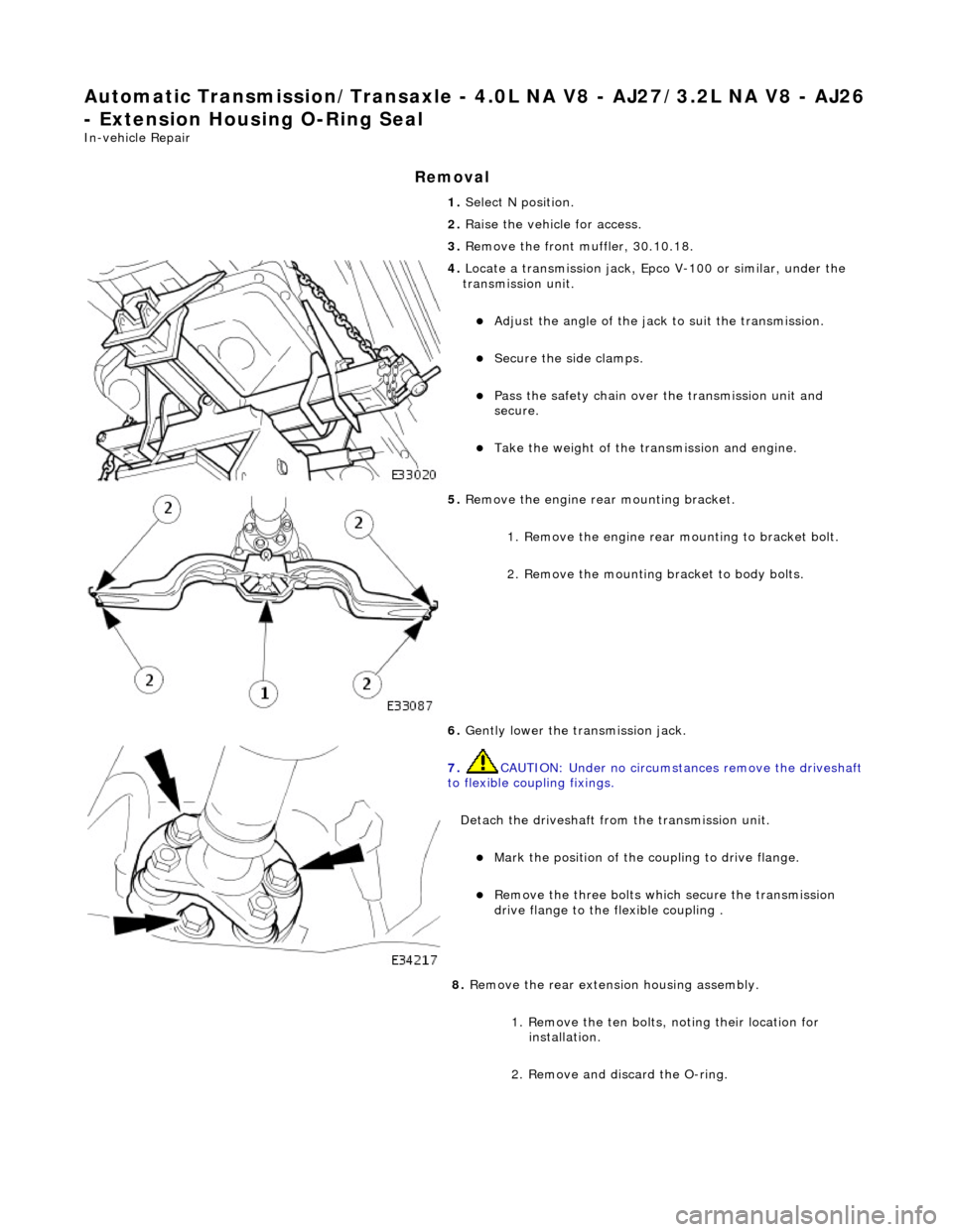
Automatic Transmission/Transaxle - 4.0L NA V8 - AJ27/3.2L NA V8 - AJ26
- Extension Housing O-Ring Seal
In-vehicle Repair
Removal
1. Select N position.
2. Raise the vehicle for access.
3. Remove the front muffler, 30.10.18.
4. Locate a transmission jack, Epco V-100 or similar, under the
transmission unit.
Adjust the angle of the jack to suit the transmission.
Secure the side clamps.
Pass the safety chain over the transmission unit and
secure.
Take the weight of the transmission and engine.
5. Remove the engine rear mounting bracket.
1. Remove the engine rear mounting to bracket bolt.
2. Remove the mounting bracket to body bolts.
6. Gently lower the transmission jack.
7. CAUTION: Under no circumstan ces remove the driveshaft
to flexible coupling fixings.
Detach the driveshaft fro m the transmission unit.
Mark the position of the coupling to drive flange.
Remove the three bolts which secure the transmission
drive flange to the flexible coupling .
8. Remove the rear extension housing assembly.
1. Remove the ten bolts, noting their location for installation.
2. Remove and discard the O-ring.
Page 1348 of 2490
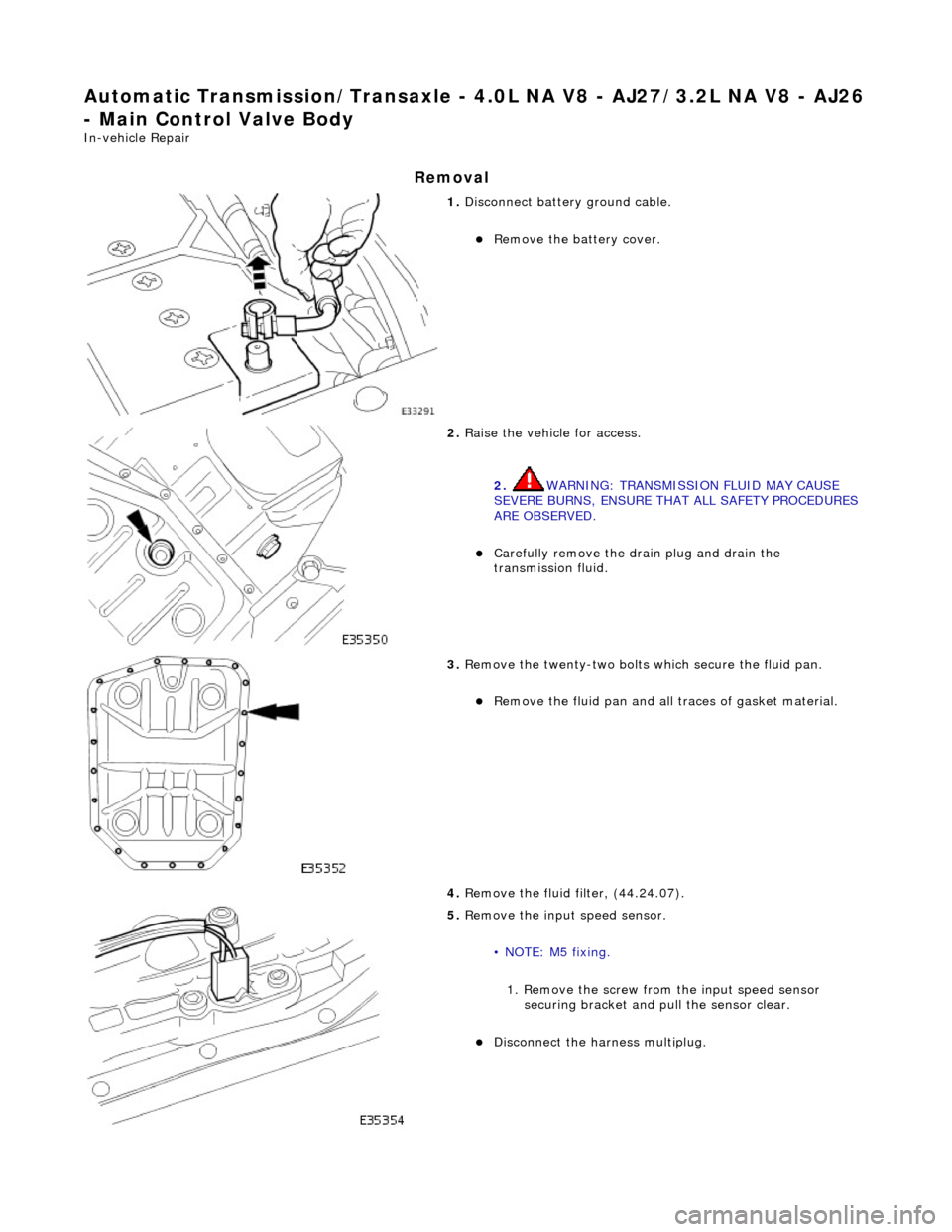
Automatic Transmission/Transaxle - 4.0L NA V8 - AJ27/3.2L NA V8 - AJ26
- Main Control Valve Body
In-vehicle Repair
Removal
1. Disconnect battery ground cable.
Remove the battery cover.
2. Raise the vehicle for access.
2. WARNING: TRANSMISSION FLUID MAY CAUSE
SEVERE BURNS, ENSURE THAT ALL SAFETY PROCEDURES
ARE OBSERVED.
Carefully remove the drain plug and drain the
transmission fluid.
3. Remove the twenty-two bolts which secure the fluid pan.
Remove the fluid pan and all tr aces of gasket material.
4. Remove the fluid filter, (44.24.07).
5. Remove the input speed sensor.
• NOTE: M5 fixing.
1. Remove the screw from the input speed sensor securing bracket and pu ll the sensor clear.
Disconnect the harness multiplug.