Page 2485 of 2490
9. Position spacer in the rece ss of each subframe bush.
10. Raise jack to locate subframe bushes on the body tapered
locations.
11. CAUTION: When installing su bframe bracket ensure that wheel speed sensor harness is clear.
Fit suspension subframe mounting-brackets.
1. Position bracket to subframe.
2. Install but do not ti ghten bush center bolt.
3. Install but do not tighten bolts securing bracket to body.
Following same procedure, install mounting bracket on
opposite side.
12. Tighten mounting bracket to body bolts to 80-100Nm.
Following same procedure, ti ghten mounting bracket bolts
on opposite side.
Page 2487 of 2490
Uni-Body, Subframe and Mounting System - Rear Axle Crossmember
Bushing
Removal and Installation
Removal
CAUTION: Replacement of nuts and bolts: Various thread-locking devices are used on nuts and bolts throughout the
vehicle. These devices restrict the number of times a nut or bolt can be used. See section 100-00 for information.
Special Tool(s)
Remover/Replacer Suspension Bushes
204-116 (JD 143A)
Remover/Replacer Adaptor
204-116-06 (JD143-6B)
1. Remove suspension subframe fro m vehicle. Refer to 64.25.20.
2. Position special tool 204-116 on the press-bed, with recesses
uppermost.
3. Remove nut and washer from tool.
Position tool on bush with recesses accommodating the
bush rebound stops.
Fit washer to tool and fit and finger tighten nut.
4. Invert subframe and position assembly on special tool 204-
116, with subframe located in the recess.
Page 2488 of 2490
Installation
5. CAUTION: Ensure special tool 204-116-06 is correctly
aligned and does not contact the bush housing bore.
Remove bush from subframe.
1. Align the top of special tool 204-116-06 with the press-ram.
2. Operate press to remove bush.
6. Remove bush from special tool and discard bush.
7. Thoroughly clean the bush-housing bore.
1. Use a coarse grade emery cloth to roughen the bush-housing
bore, and mating surface of the bush.
2. Using an air line, remove residu al dust from bush and housing
mating surfaces.
3. Clean the bush-housing bore and bush with cleaning solvent
(SPB3 Solvent 30) or equivalent.
4. Invert suspension subframe.
5. Mark bush position on sub-frame.
1. Stretch a length of thin co rd across the center line of
each bush location.
2. Below the string, place two pieces of masking tape diametrically opposite on the bore periphery.
3. Mark string position on the masking tape.
Page 2489 of 2490

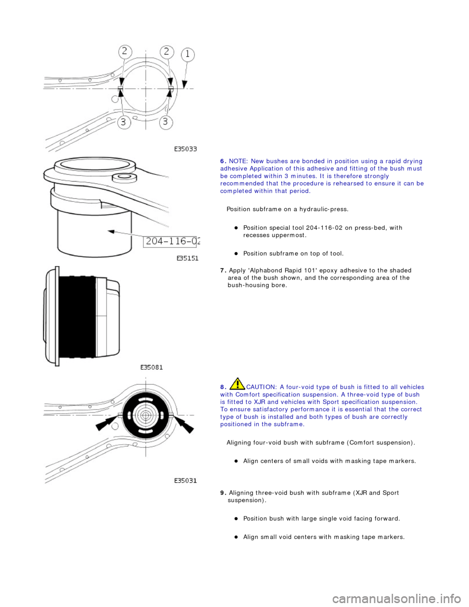
6. NOTE: New bushes are bonded in position using a rapid drying
adhesive Application of this adhesive and fitting of the bush must
be completed within 3 minutes. It is therefore strongly
recommended that the procedure is rehearsed to ensure it can be
completed within that period.
Position subframe on a hydraulic-press.
Position special tool 204-116-02 on press-bed, with
recesses uppermost.
Position subframe on top of tool.
7. Apply 'Alphabond Rapid 101' epoxy adhesive to the shaded
area of the bush shown, and the corresponding area of the
bush-housing bore.
8. CAUTION: A four-void type of bu sh is fitted to all vehicles
with Comfort specification suspension. A three-void type of bush
is fitted to XJR and vehicles with Sport specification suspension.
To ensure satisfactory performance it is essential that the correct
type of bush is installed and bo th types of bush are correctly
positioned in the subframe.
Aligning four-void bush with su bframe (Comfort suspension).
Align centers of small voids with masking tape markers.
9. Aligning three-void bush wi th subframe (XJR and Sport
suspension).
Position bush with large single void facing forward.
Align small void centers with masking tape markers.
Page 2490 of 2490
10. Install bush in housing.
Position a steel plate over the bush, ensuring the plate is
large enough to cover the rubber flange.
Operate the press to install the bush.
11. Ensure bush is fully seated in subframe.
The clearance between the bush flange and subframe
must not exceed 1.5 mm.
12. Ensure bush is aligned correctly in subframe as detailed in
Step 8 or 9 as appropriate.
13. Wipe off all excess adhesive from subframe and bush, and
remove masking tape.
14. NOTE: Allow adhesive at leas t 30 minutes to cure, before
installing subframe on vehicle.
Install suspension subframe on vehicle. Refer to 64..25.20.
Page:
< prev 1-8 9-16 17-24