Page 2148 of 2490
Installation
8. Withdraw LH slide from seat motor potentiometer/gearbox
assembly.
1. Fit and fully seat slide to po tentiometer/gearbox assembly.
2. Position motor frame on slide assembly and secure with new
pop rivets.
3. Connect seat cushion tilt motor drive cables.
4. Secure seat harness in clips.
5. Position slide assembly on seat.
6. Fit and align RH seat belt bu ckle mounting bracket between
slide and seat pivot bracket and fit but do not tighten securing
bolts.
7. Fit and align LH seat belt an chor bracket between slide and
seat pivot bracket an d fit but do not tighten securing bolts.
8. Fit but do not tighten RH and LH slide front securing bolts.
9. Finally tighten slide front and rear securing bolts.
10. Fit front seat to vehi cle. Refer to 76.70.01.
Page 2152 of 2490
16. Slacken and remove bolt securi ng motor/ potentiometer and
gearbox to LH slider and re move LH slider assembly.
17. Release motor/potentiometer an d gearbox harness multiplug
from mounting bracket an d disconnect multiplug.
18. Slacken and remove motor/pote ntiometer to frame securing
bolts.
19. Disconnect RH seat slider gearbox drive cable from
motor/potentiometer.
Page 2153 of 2490

I
nstallation
20
.
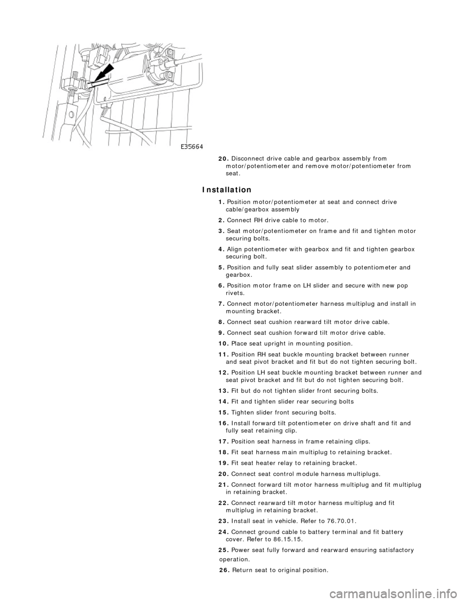
Disconnect drive cable and gearbox assembly from
motor/potentiometer and remo ve motor/potentiometer from
seat.
1. Position motor/potentiometer at seat and connect drive
cable/gearbox assembly
2. Connect RH drive cable to motor.
3. Seat motor/potentiometer on fra me and fit and tighten motor
securing bolts.
4. Align potentiometer with gearbo x and fit and tighten gearbox
securing bolt.
5. Position and fully seat slider assembly to potentiometer and
gearbox.
6. Position motor frame on LH sl ider and secure with new pop
rivets.
7. Connect motor/potentiometer harness multiplug and install in
mounting bracket.
8. Connect seat cushion rearward tilt motor drive cable.
9. Connect seat cushion forwar d tilt motor drive cable.
10. Place seat upright in mounting position.
11. Position RH seat buckle mounting bracket between runner
and seat pivot bracket and fit but do not tighten securing bolt.
12. Position LH seat buckle mounting bracket between runner and
seat pivot bracket an d fit but do not tighten securing bolt.
13. Fit but do not tighten slider front securing bolts.
14. Fit and tighten slider rear securing bolts
15. Tighten slider front securing bolts.
16. Install forward tilt potentiome ter on drive shaft and fit and
fully seat retaining clip.
17. Position seat harness in frame retaining clips.
18. Fit seat harness main multiplug to retaining bracket.
19. Fit seat heater relay to retaining bracket.
20. Connect seat control module harness multiplugs.
21. Connect forward tilt motor harn ess multiplug and fit multiplug
in retaining bracket.
22. Connect rearward tilt motor harness multiplug and fit
multiplug in retaining bracket.
23. Install seat in vehicle. Refer to 76.70.01.
24. Connect ground cable to batt ery terminal and fit battery
cover. Refer to 86.15.15.
25. Power seat fully forward and rearward ensuring satisfactory
op
eration.
26. Return seat to original position.
Page 2329 of 2490

Roof Opening Panel - Motor Synchronization
General Procedures
1.
Remove sliding roof trim panel for access. Refer to 76.82.19.
2. Remove battery cover and disc onnect ground cable from
battery terminal. Refer to 86.15.19.
3. Remove roof console for ac cess. Refer to 76.13.69.90.
4. Remove sliding roof panel cont rol module. Refer to 86.76.07.
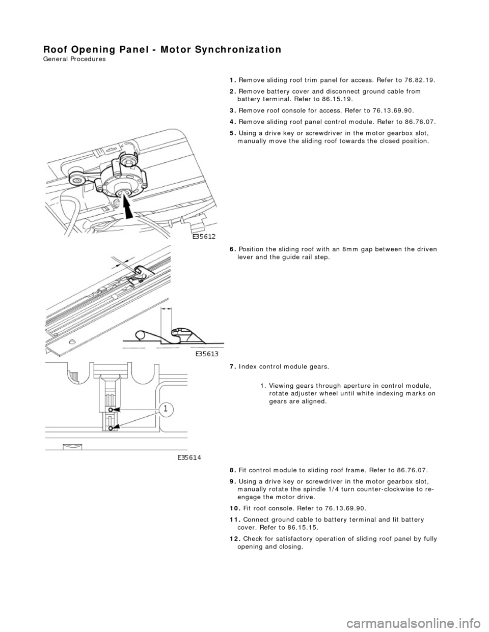
5. Using a drive key or screwdriver in the motor gearbox slot,
manually move the sliding roof towards the closed position.
6. Position the sliding roof with an 8mm gap between the driven
lever and the guide rail step.
7. Index control module gears.
1. Viewing gears through aperture in control module, rotate adjuster wheel until white indexing marks on
gears are aligned.
8. Fit control module to sliding r oof frame. Refer to 86.76.07.
9. Using a drive key or screwdriver in the motor gearbox slot,
manually rotate the spindle 1/4 turn counter-clockwise to re-
engage the motor drive.
10. Fit roof console. Refer to 76.13.69.90.
11. Connect ground cable to batt ery terminal and fit battery
cover. Refer to 86.15.15.
12. Check for satisfactory operation of sliding roof panel by fully
opening and closing.
Page 2335 of 2490
Roof Opening Panel - Roof Opening Panel Module
Removal and Installation
Removal
1. Remove cover from battery and disconnect ground cable from
battery terminal.
2. Remove sliding roof trim panel for access. Refer to 76.82.19.
3. Using a drive key or screwdriver in the motor gearbox slot,
manually move the sliding roof towards the closed position.
4. Position the sliding roof with an 8mm gap between the driven
lever and the guide rail step.
5. Remove roof console for ac cess. Refer to 76.13.69.90.
6. Release sun visor from support and position at cantrail.
7. Remove visor support securing screw and remove support from
header.
8. Disconnect harness multiplugs from sliding roof control
module.
9. Carefully withdraw adjacent sectio n of flange finisher and edge
of headlining sufficient to prov ide access to control module.
10. Depressing retaining tang on RH side of module, lower that
side and release from tang on sliding roof frame.
Page 2336 of 2490

Installation
1. Synchronise control module gears. Refer to 76.82.48.
2. Exercising care to avoid da maging edge, lower front of
headlining for access.
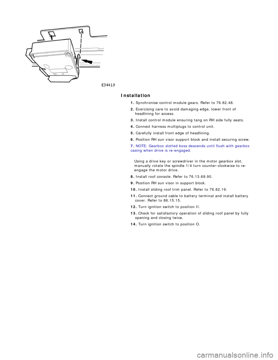
3. Install control module ensuring tang on RH side fully seats.
4. Connect harness multiplugs to control unit.
5. Carefully install front edge of headlining.
6. Position RH sun visor support bl ock and install securing screw.
7. NOTE: Gearbox slotted boss descends until flush with gearbox
casing when drive is re-engaged.
Using a drive key or screwdriver in the motor gearbox slot,
manually rotate the spindle 1/4 turn counter-clockwise to re-
engage the motor drive.
8. Install roof console. Refer to 76.13.69.90.
9. Position RH sun visor in support block.
10. Install sliding roof trim panel. Refer to 76.82.19.
11. Connect ground cable to batter y terminal and install battery
cover. Refer to 86.15.15.
12. Turn ignition switch to position II.
13. Check for satisfactory operation of sliding roof panel by fully
opening and closing twice.
14. Turn ignition switch to position O.
Page 2338 of 2490
3. Fit and tighten motor securing screws.
4. Connect motor harness multiplug to control module.
5. Using a drive key or screwdriver in the motor gearbox slot,
manually rotate the spindle 1/4 turn counter-clockwise to re-
engage the motor drive.
6. Fit roof console. Refer to 76.13.69.90.
7. Connect ground cable to battery terminal and fit battery cover.
Refer to 86.15.15.
Page 2405 of 2490

On North American specification vehicles, the VIN is marked on all major external panels, certain structural members and
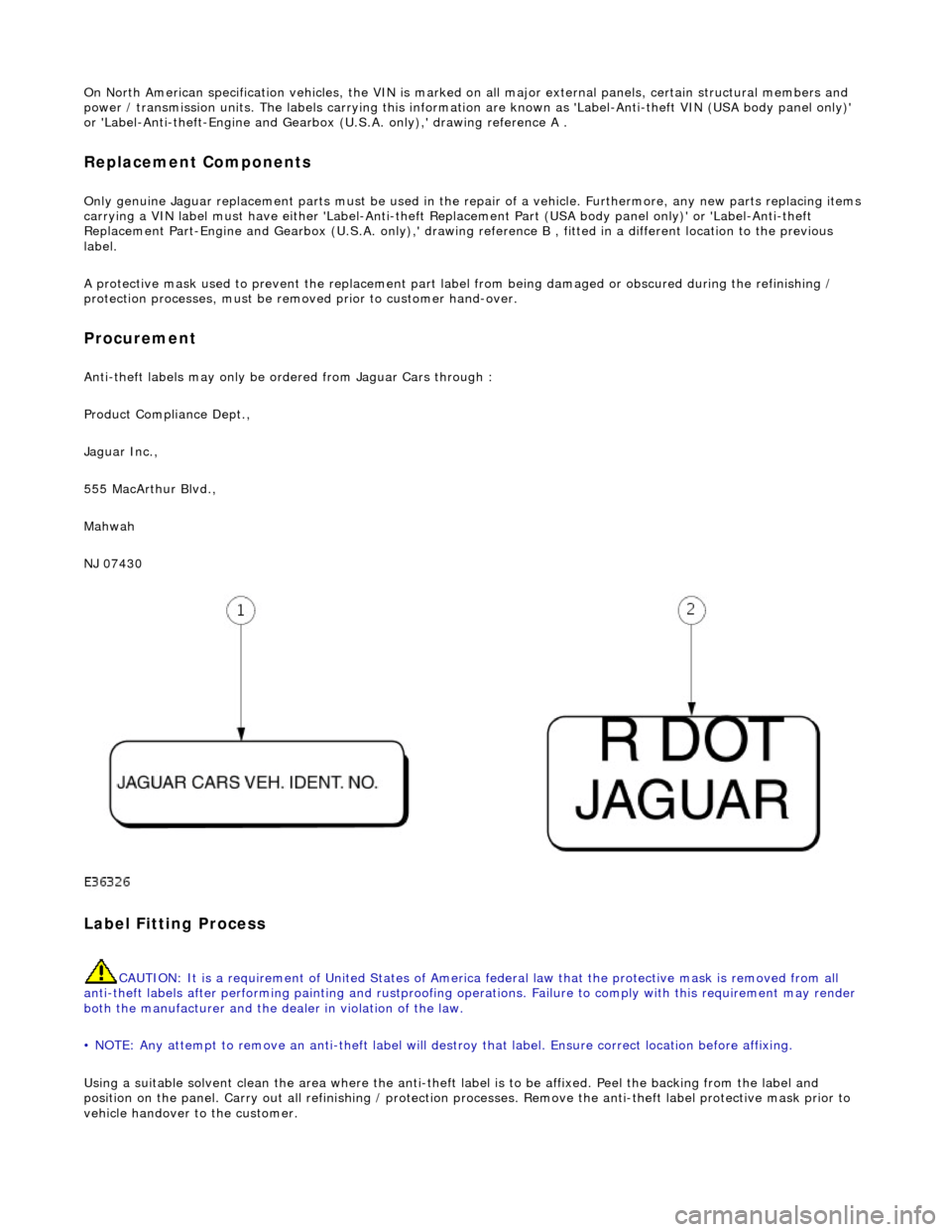
power / transmission units. The labels ca rrying this information are known as 'Label-Anti-theft VIN (USA body panel only)'
or 'Label-Anti-theft-Engine and Gearbo x (U.S.A. only),' drawing reference A .
Replacement Components
Only genuine Jaguar replacement parts must be used in the repair of a vehicle. Furthermore, any new parts replacing items
carrying a VIN label must have either 'Label-Anti-theft Replacement Part (USA body panel only)' or 'Label-Anti-theft
Replacement Part-Engine and Gearbox (U.S.A . only),' drawing reference B , fitted in a different location to the previous
label.
A protective mask used to prevent the replacement part la bel from being damaged or obscured during the refinishing /
protection processes, must be remo ved prior to customer hand-over.
Procurement
Anti-theft labels may only be ordered from Jaguar Cars through :
Product Compliance Dept.,
Jaguar Inc.,
555 MacArthur Blvd.,
Mahwah
NJ 07430
Label Fitting Process
CAUTION: It is a requirement of United States of America federal law th at the protective mask is removed from all
anti-theft labels after performing painting and rustproofing operations. Fail ure to comply with this requirement may render
both the manufacturer and the de aler in violation of the law.
• NOTE: Any attempt to remove an anti-t heft label will destroy that label. Ensure correct location before affixing.
Using a suitable solvent clean the area where the anti-theft label is to be affixed. Peel the backing from the label and
position on the panel. Carry out all refini shing / protection processes. Remove the anti-theft label protective mask prior to
vehicle handover to the customer.
Page:
< prev 1-8 9-16 17-24