1998 JAGUAR X308 diagram
[x] Cancel search: diagramPage 1068 of 2490
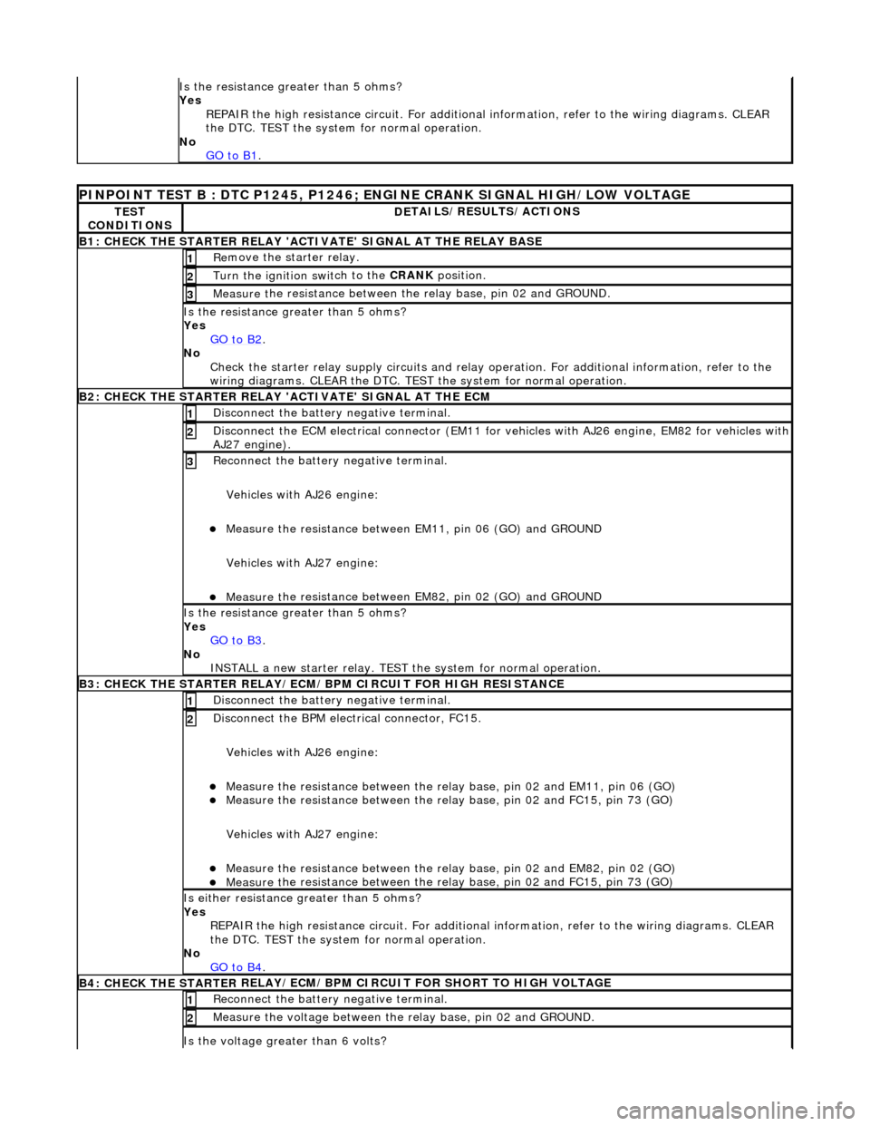
Is the res
istance greater than 5 ohms?
Yes REPAIR the high resistance circui t. For additional information, refer to the wiring diagrams. CLEAR
the DTC. TEST the system for normal operation.
No GO to B1
.
PINPOINT TES
T B : DTC P1245, P1246; ENGINE CRANK SIGNAL HIGH/LOW VOLTAGE
TE
S
T
CONDITIONS
D E
TAILS/RESULTS/ACTIONS
B1: CHECK
THE STARTER
RELAY 'ACTIV
ATE' SIGNAL AT THE RELAY BASE
Re
move the starter relay.
1
Turn the ignition swi
t
ch to the CRANK
position.
2
Measure t
he resistance between th
e relay base, pin 02 and GROUND.
3
Is the res
istance greater than 5 ohms?
Yes GO to B2
.
No Check t
he starter relay supply circui
ts and relay operation. For additi onal information, refer to the
wiring diagrams. CLEAR the DTC. TEST the system for normal operation.
B2: CHECK THE STARTER
RELAY 'A
CTIVATE' SIGNAL AT THE ECM
Disc
onnect the battery negative terminal.
1
D
i
sconnect the ECM electrical connector (EM11 for vehicles with AJ26 engine
, EM82 for vehicles with
AJ27 engine).
2
R e
connect the battery negative terminal.
Vehicles with AJ26 engine:
Meas ure t
he resistance between EM11, pin 06 (GO) and GROUND
Vehicles with AJ27 engine:
Meas ure t
he resistance between EM82, pin 02 (GO) and GROUND
3
Is th
e res
istance greater than 5 ohms?
Yes GO to B3
.
No
IN
STALL a new starter relay. TEST
the system for normal operation.
B3: CHECK THE STARTER
RELAY/ECM/BPM CIRCUIT FOR HIGH RESISTANCE
Di sc
onnect the battery negative terminal.
1
Disc
onne
ct the BPM electrical connector, FC15.
Vehicles with AJ26 engine:
Meas ure t
he resistance between the relay
base, pin 02 and EM11, pin 06 (GO)
Measure t
he resistance between the relay
base, pin 02 and FC15, pin 73 (GO)
Vehicles with AJ27 engine:
Meas ure t
he resistance between the relay
base, pin 02 and EM82, pin 02 (GO)
Measure t
he resistance between the relay
base, pin 02 and FC15, pin 73 (GO)
2
Is either resistance greater
than 5 ohms?
Yes REPAIR the high resistance circui t. For additional information, refer to the wiring diagrams. CLEAR
the DTC. TEST the system for normal operation.
No GO to B4
.
B4: CHECK THE STARTER
RE
LAY/ECM/BPM CIRCUIT FOR SHORT TO HIGH VOLTAGE
Re
connect the battery negative terminal.
1
Meas
ure t
he voltage between the
relay base, pin 02 and GROUND.
2
Is the volt
age greater than 6 volts?
Page 1069 of 2490
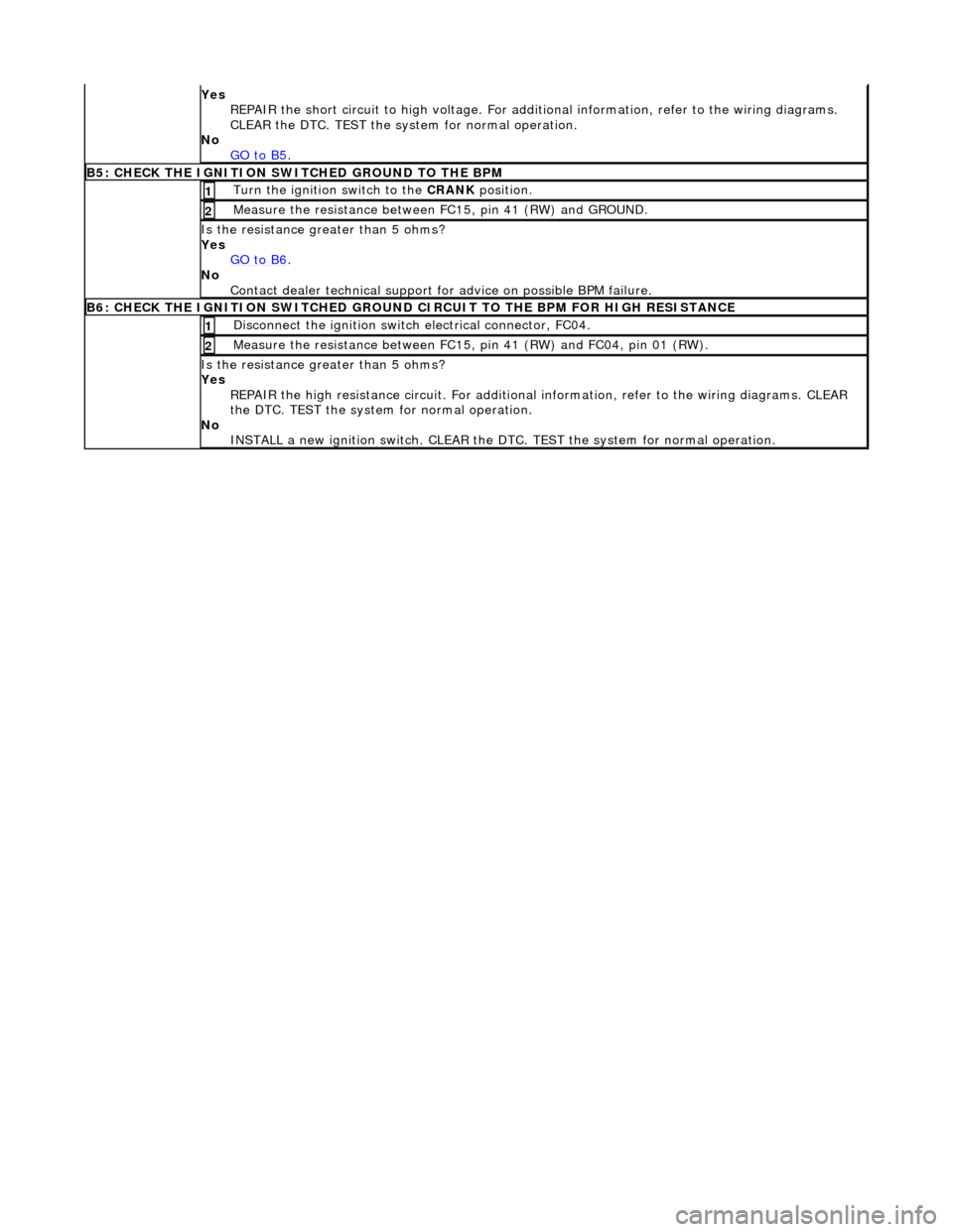
Yes
REPAIR the short circuit to high voltage. For addi tional information, refer to the wiring diagrams.
CLEAR the DTC. TEST the syst em for normal operation.
No GO to B5
.
B5: CHECK
THE IGNITION SWITCHED GROUND TO THE BPM
Turn the ignition swi
tch to the CRANK
position.
1
Meas
ure the resistance between FC15, pin 41 (RW) and GROUND.
2
Is th
e resistance greater than 5 ohms?
Yes GO to B6
.
No
Contact dealer technical support fo r advice on possible BPM failure.
B6: CHECK
THE IGNITION SWIT
CHED GROUND CIRCUIT TO THE BPM FOR HIGH RESISTANCE
Di
sconnect the ignition switch electrical connector, FC04.
1
Meas
ure the resistance between FC15,
pin 41 (RW) and FC04, pin 01 (RW).
2
Is th
e resistance greater than 5 ohms?
Yes REPAIR the high resistance circui t. For additional information, refer to the wiring diagrams. CLEAR
the DTC. TEST the system for normal operation.
No INSTALL a new ignition switch. CLEAR the DTC. TEST the system for normal operation.
Page 1073 of 2490
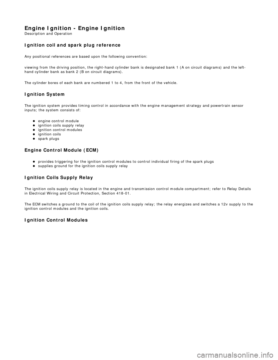
Engine Igni
tion -
Engine Ignition
Description an
d Operation
I
gnition coil and spark plug reference
Any positional r
eferences are base
d upon the following convention:
viewing from the driving position, the right-hand cylinder bank is designated bank 1 (A on circuit diagrams) and the left-
hand cylinder bank as bank 2 (B on circuit diagrams).
The cylinder bores of each bank are number ed 1 to 4, from the front of the vehicle.
Ig
nition System
Th
e ignition system provides timing cont
rol in accordance with the engine mana gement strategy and powertrain sensor
inputs; the system consists of:
engine
control module
igni
tion coils supply relay
ignit
ion control modules
igni
tion coils
spark plu
gs
Engine Control Module (ECM)
pr
ovides triggering for the ignition control modules
to control individual firing of the spark plugs
supplies ground for
the igni
tion coils supply relay
I
gnition Coils Supply Relay
The
ignition coils supply relay is located
in the engine and transmission control mo dule compartment; refer to Relay Details
in Electrical Wiring and Circuit Protection, Section 418-01.
The ECM switches a ground to the coil of the ignition coils supply relay; the relay energizes and switches a 12v supply to the
ignition control modules and the ignition coils.
I
gnition Control Modules
Page 1076 of 2490
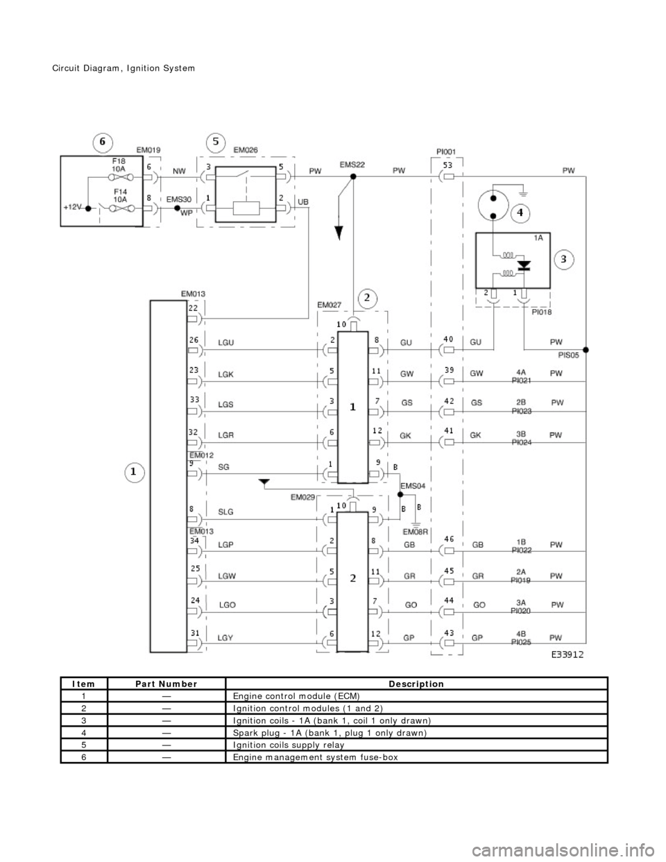
It e
m
Par
t
Number
De
scr
iption
1—Engine
control module (E
CM)
2—Ignition control
modules (1 and 2)
3—Igniti
on coils - 1A (bank 1, coil 1 only drawn)
4—Spark
plug - 1
A (bank 1, plug 1 only drawn)
5—Igni
ti
on coils supply relay
6—Engine
management system fuse-box
Ci
rcui
t Diagram,
Ignition System
Page 1084 of 2490
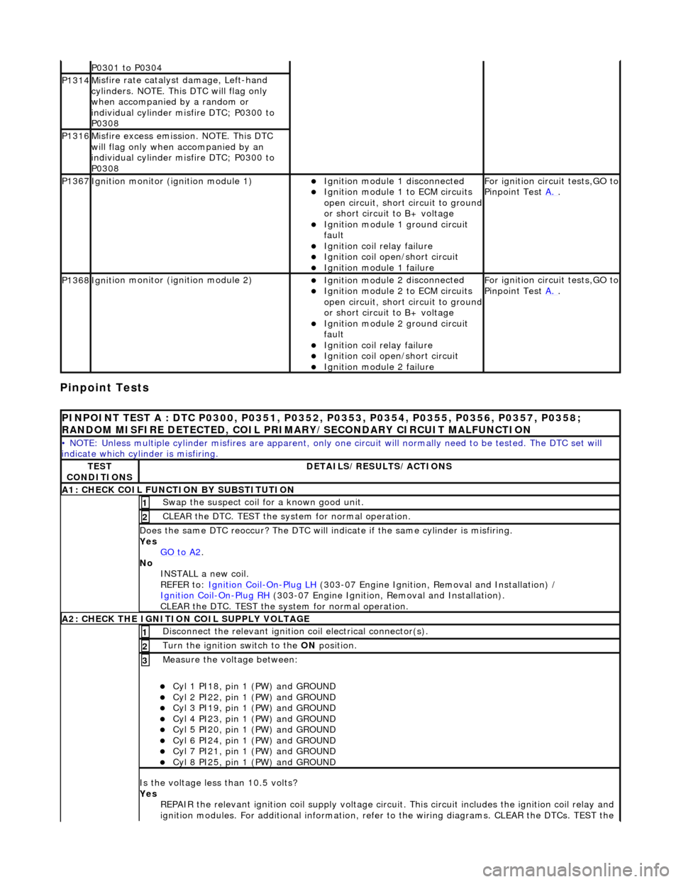
Pinpoint Tests
P0301 t
o P0304
P1314M
i
sfire rate catalyst damage, Left-hand
cylinders. NOTE. This DTC will flag only
when accompanied by a random or
individual cylinder misfire DTC; P0300 to
P0308
P1316M i
sfire excess emission. NOTE. This DTC
will flag only when accompanied by an
individual cylinder misfire DTC; P0300 to
P0308
P1367Ignit i
on monitor (ignition module 1)
Ignition modu
le
1 disconnected
Ignition modul e
1 to ECM circuits
open circuit, short circuit to ground
or short circuit to B+ voltage
Ignition modul e
1 ground circuit
fault
Ignition coil relay fai
lure
Ignition coil open/short
circuit
Ignition module
1 failure
F
o
r ignition circuit tests,GO to
Pinpoint Test A.
.
P1368Igniti
on monitor (ignition module 2)
Ignition modu
le
2 disconnected
Ignition modul e
2 to ECM circuits
open circuit, short circuit to ground
or short circuit to B+ voltage
Ignition modul e
2 ground circuit
fault
Ignition coil relay fai
lure
Ignition coil
open/short
circuit
Ignition modul
e
2 failure
F
o
r ignition circuit tests,GO to
Pinpoint Test A.
.
PINPOINT TES
T A : DTC P0300, P0351, P0352, P0353, P0354, P0355, P0356, P0357, P0358;
RANDOM MISFIRE DETECTED, COIL PRIMARY/SECONDARY CIRCUIT MALFUNCTION
• NO
TE: Unless multiple cylinder misfires are apparent, only on
e circuit will normally need to be tested. The DTC set will
indicate which cylinder is misfiring.
TE S
T
CONDITIONS
D E
TAILS/RESULTS/ACTIONS
A1
: CH
ECK COIL FUNCTI
ON BY SUBSTITUTION
Swap the suspect coi l
for a known good unit.
1
CLEAR t
h
e DTC. TEST the syst
em for normal operation.
2
Do
es the same DTC reoccur? The DTC will indicate if the same cylinder is misfiring.
Yes GO to A2
.
No
INST
ALL a new coil.
REFER to: Ignition Coil
-On-Plug
LH
(30
3-07 Engine Ignition, Removal and Installation) /
Ignition Coil
-On-Plu g
RH
(30
3-07 Engine Ignition, Removal and Installation).
CLEAR the DTC. TEST the system for normal operation.
A2: CHECK THE IGNIT
ION COIL SUPPLY VOLTAGE
Disc
onne
ct the relevant ignition
coil electrical connector(s).
1
Turn the ignition swit
ch to the ON
position.
2
Measure the voltage between:
Cyl 1 PI18, pin
1 (PW) and GROUND
Cy
l 2 PI22, pin
1 (PW) and GROUND
Cy
l 3 PI19, pin
1 (PW) and GROUND
Cy
l 4 PI23, pin
1 (PW) and GROUND
Cy
l 5 PI20, pin
1 (PW) and GROUND
Cy
l 6 PI24, pin
1 (PW) and GROUND
Cy
l 7 PI21, pin
1 (PW) and GROUND
Cy
l 8 PI25, pin
1 (PW) and GROUND
3
Is
t
he voltage less than 10.5 volts?
Yes REPAIR the relevant ignition coil su pply voltage circuit. This circuit includes the ignition coil relay and
ignition modules. For additional information, refer to the wiring diagrams. CLEAR the DTCs. TEST the
Page 1085 of 2490
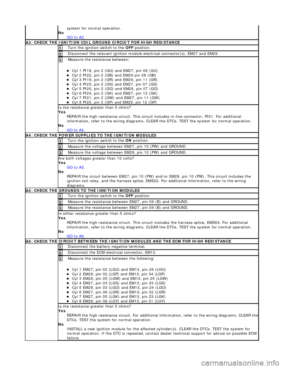
system fo
r normal operation.
No GO to A3
.
A3
: CHECK THE IGNITION COIL GROUND CIRCUIT FOR HIGH RESISTANCE
Turn the ignition swi
tch to the OFF
position.
1
Disc
onnect the relevant ignition module
electrical connector(s), EM27 and EM29.
2
Meas
ure the resistance between:
Cy
l 1 PI18, pin 2 (GU) and EM27, pin 08 (GU)
Cy
l 2 PI22, pin 2 (GB) and EM29 pin 08 (GB)
Cy
l 3 PI19, pin 2 (GR) and EM29, pin 11 (GR)
Cy
l 4 PI23, pin 2 (GS)
and EM27, pin 07 (GS)
Cy
l 5 PI20, pin 2 (GO) and EM29, pin 07 (GO)
Cy
l 6 PI24, pin 2 (GK) and EM27, pin 12 (GK)
Cy
l 7 PI21, pin 2 (GW) and EM27, pin 11 (GW)
Cy
l 8 PI25, pin 2 (GP) an
d EM29, pin 12 (GP)
3
Is th
e resistance greater than 5 ohms?
Yes REPAIR the high resistance circui t. This circuit includes in-line connector, PI01. For additional
information, refer to the wiring diagrams. CLEAR the DTCs. TEST the system for normal operation.
No GO to A4
.
A4:
CHECK THE POWER SUPPLIES TO THE IGNITION MODULES
Turn the ignition swi
tch to the ON
position.
1
Meas
ure the voltage between EM27, pin 10 (PW) and GROUND.
2
Meas
ure the voltage between EM29, pin 10 (PW) and GROUND.
3
Are both
voltages greater than 10 volts?
Yes GO to A5
.
No
REPAIR the circuit between EM27, pin 10 (PW) and/or EM29, pin 10 (PW). This circuit includes the
ignition coil relay, and the harness splice, EMS22. For additional information, refer to the wiring
diagrams.
A5:
CHECK THE GROUNDS TO THE IGNITION MODULES
Turn the ignition swi
tch to the OFF
position.
1
Meas
ure the resistance between EM27, pin 09 (B) and GROUND.
2
Meas
ure the resistance between EM27, pin 09 (B) and GROUND.
3
Is either resi
stance
greater than 5 ohms?
Yes REPAIR the high resistance circui t. This circuit includes the harness splice, EMS04. For additional
information, refer to the wiring diagrams. CLEAR the DTCs. TEST the system for normal operation.
No GO to A6
.
A6: CHECK
THE CIRCUIT BETWEEN THE IGNITION
MODULES AND THE ECM FOR HIGH RESISTANCE
Di
sconnect the battery negative terminal.
1
D
isconnect the ECM electrical connector, EM13.
2
Meas
ure the resistance between the following:
Cy
l 1 EM27, pin 02 (LGU) and EM13, pin 26 (LGU)
Cy
l 2 EM29, pin 02 (LGP) and EM13, pin 34 (LGP)
Cy
l 3 EM29, pin 05 (LGW) and EM13, pin 25 (LGW)
Cy
l 4 EM27, pin 03 (LGS) and EM13, pin 33 (LGS)
Cy
l 5 EM29, pin 03 (LGO) and EM13, pin 24 (LGO)
Cy
l 6 EM27, pin 06 (LGR) and EM13, pin 32 (LGR)
Cy
l 7 EM27, pin 05 (LGK) and EM13, pin 23 (LGK)
Cy
l 8 EM29, pin 06 (LGY) and EM13, pin 31 (LGY)
3
Is th
e resistance greater than 5 ohms?
Yes REPAIR the high resistance circuit. For additional information, refer to the wiring diagrams. CLEAR the
DTCs. TEST the system for normal operation.
No INSTALL a new ignition module for the affected cy linder(s). CLEAR the DTCs. TEST the system for
normal operation. If the DTC is re peated, contact dealer technical support for advice on possible ECM
failure.
Page 1096 of 2490
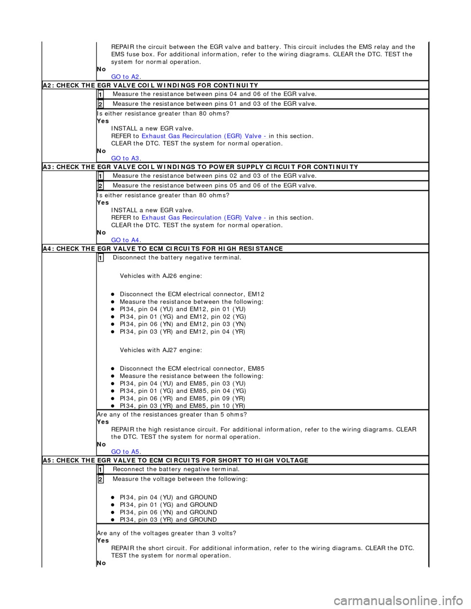
RE
PAIR the circuit between the EGR valve and battery. This circuit includes the EMS relay and the
EMS fuse box. For additional info rmation, refer to the wiring diagrams. CLEAR the DTC. TEST the
system for normal operation.
No GO to A2
.
A2: CHECK THE EGR VALVE COIL WIND
INGS FOR CONTINUITY
Meas
ure t
he resistance between pins 04 and 06 of the EGR valve.
1
Meas
ure t
he resistance between pins 01 and 03 of the EGR valve.
2
Is either resi
stance
greater
than 80 ohms?
Yes INSTALL a new EGR valve.
REFER to Exhaust Gas Recirculation (EGR) Valve
- in thi
s section.
CLEAR the DTC. TEST the syst em for normal operation.
No GO to A3
.
A3: CHECK THE EGR VALVE COIL WINDINGS TO
POWER SUPPLY CIRCUIT FOR CONTINUITY
Meas
ure t
he resistance between pins 02 and 03 of the EGR valve.
1
Meas
ure t
he resistance between pins 05 and 06 of the EGR valve.
2
Is either resi
stance greater
than 80 ohms?
Yes INSTALL a new EGR valve.
REFER to Exhaust Gas Recirculation (EGR) Valve
- in thi
s section.
CLEAR the DTC. TEST the syst em for normal operation.
No GO to A4
.
A4: CHECK THE EGR VALVE T
O ECM
CIRCUITS FOR HIGH RESISTANCE
Disc
onnect the battery negative terminal.
Vehicles with AJ26 engine:
D i
sconnect the ECM electrical connector, EM12
Meas
ure t
he resistance between the following:
PI34, pin
0
4 (YU) and EM12, pin 01 (YU)
PI34,
pi
n 01 (YG) and EM12, pin 02 (YG)
PI34, pin
0
6 (YN) and EM12, pin 03 (YN)
PI34,
pi
n 03 (YR) and EM12, pin 04 (YR)
Vehicles with AJ27 engine:
D i
sconnect the ECM electrical connector, EM85
Meas
ure t
he resistance between the following:
PI34, pin
0
4 (YU) and EM85, pin 03 (YU)
PI34, pi
n 01 (YG) and EM85, pin 04 (YG)
PI34, pi
n 06 (YR) and EM85, pin 09 (YR)
PI34, pi
n 03 (YR) and EM85, pin 10 (YR)
1
Are an
y of the resistances greater than 5 ohms?
Yes REPAIR the high resistance circui t. For additional information, refer to the wiring diagrams. CLEAR
the DTC. TEST the system for normal operation.
No GO to A5
.
A5: CHECK THE EGR VALVE T
O ECM CIRCUITS FOR SHORT TO HIGH VOLTAGE
R
e
connect the battery negative terminal.
1
Meas
ure t
he voltage between the following:
PI34, pin
0
4 (YU) and GROUND
PI34, pin
0
1 (YG) and GROUND
PI34, pin
0
6 (YN) and GROUND
PI34, pin
0
3 (YR) and GROUND
2
Are any of th
e volt
ages greater than 3 volts?
Yes REPAIR the short circuit. For addi tional information, refer to the wiring diagrams. CLEAR the DTC.
TEST the system for normal operation.
No
Page 1097 of 2490
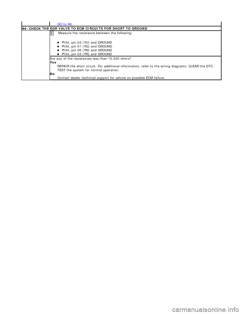
GO to A6.
A6: CHECK
THE EGR VALVE TO ECM
CIRCUITS FOR SHORT TO GROUND
Meas
ure the resistance between the following:
PI34, pin
04 (YU) and GROUND
PI34, pin
01 (YG) and GROUND
PI34, pin
06 (YN) and GROUND
PI34, pin
03 (YR) and GROUND
1
Are
any of the resistances less than 10,000 ohms?
Yes REPAIR the short circuit. For addi tional information, refer to the wiring diagrams. CLEAR the DTC.
TEST the system for normal operation.
No Contact dealer technical support for advice on possible ECM failure.