Page 935 of 2490

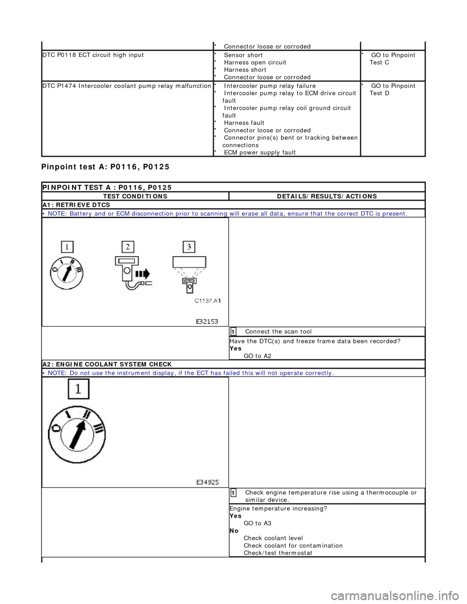
Pinpoint test
A: P0116, P0125
Connector
loose or corroded
*
D
TC P0118 ECT circuit high input
Sensor short
Harness open circui
t
Harness short
Connector loose or corroded
*
*
*
*
GO to Pinpoint
Test C
*
D
TC P1474 Intercooler coolant pump relay malfunction
Intercooler pump relay
failure
Intercooler pump relay to ECM drive circuit
fault Intercooler pump relay coil ground circuit
fault Harness fault
Connector loose or corroded
Connector pins(s) bent or tracking between
connections ECM power supply fault
*
*
*
*
*
*
*
GO to Pinpoint
Test D
*
P
INPOINT TEST A : P0116, P0125
T
EST CONDITIONS
D
ETAILS/RESULTS/ACTIONS
A1
: RETRIEVE DTCS
•
NOTE: Battery and or ECM disconnection prior to scanning wi
ll erase all data, ensure that the correct DTC is present.
Conne
ct the scan tool
1
Have the DTC(s) and fr
eeze
frame data been recorded?
Yes GO to A2
A2: ENGINE
COOLANT SYSTEM CHECK
•
NOTE: Do not use the instrument display, if th
e ECT has failed this will not operate correctly.
Chec
k engine temperature rise using a thermocouple or
similar device.
1
Engine
temperature increasing?
Yes GO to A3
No Check coolant level
Check coolant for contamination
Check/test thermostat
Page 962 of 2490

All vehicles
21.
N
OTE: Install a new sealing washer.
• NOTE: Clean off any spillages.
Install the supercharger coolant fill plug.
Tighte
n to 45 Nm.
22. Remove the coolant expans ion tank pressure cap.
23. Switch ignition on.
24. CAUTION: Do not allow the supercharger water pump to
run dry. Failure to follow this instruction may result in damage to
the vehicle.
• NOTE: Leave the ignition switched on (do not start the engine)
for at least 2 minutes to allow the air charge cooler electric water
pump to operate and to purge an y air from the air charge cooler
radiator to the header tank.
Allow the supercharger pump to run and top up the system
through the coolant expansion tank.
25 . Swit
ch the ignition off.
26. Install the coolant expansion tank pressure cap.
27. START and RUN the engine.
28. CAUTION: Observe the engine temperature gauge. If
the engine starts to over-heat switch off immediately and allow to
cool. Failure to follow this inst ruction may cause damage to the
vehicle.
Run the engine at between 1500 and 2000 rpm until the cooling
fan operates.
29 .
Swi
tch off the engine.
30. Allow the engine to cool.
31. Check and top-up the coolant if required.
Page 965 of 2490

Engine Cooling - Coolant Outlet Pipe
Re
moval and Installation
Remov
al
Installation
1.
O
pen the engine compartment and fit paintwork protection
sheets.
2. Drain the radiator. Refer to Ge neral Procedures. Retain the
coolant drain tray in position to catch any spillage when
removing the outlet pipe.
3. Di
sconnect the hoses and multi-plug from the coolant outlet
pipe.
1. Release and reposition th e hose clip, and disconnect
the top hose.
2. Release and reposition th e hose clip, and disconnect
the heater hose.
3. Disconnect the multi-plug from the temperature sensor and unscrew the sens or from the outlet pipe.
4. Release and reposition the hose clip along the bypass
hose.
4. R
emove the coolant outlet pipe.
1. Remove the four bolts which secure the outlet pipe.
2. Remove the outlet pipe from the bypass hose and
from the cylinder heads.
5. Remove and discard the sealing rings from the outlet pipe
grooves.
1. Installation is the reverse of the remova l procedure. Use new
sealing rings on the coolant outlet pipe.
2. Tighten the coolant outlet pipe bolts to 10-14 Nm If replacing
the coolant temperature sensor, tighten to 15-19 Nm.
3. Refill the cooling system as de scribed in General Procedures.
Page 966 of 2490

Engine Cooling - Coolant Outlet Pipe
Remo
val and Installation
Remov
a
l
1.
Op
en the engine compartment and fit paintwork protection
sheets.
2. Drain the radiator. Refer to Ge neral Procedures. Retain the
coolant drain tray in position to catch any spillage when
removing the outlet pipe.
3. Disc onne
ct the top hose and br
eather pipe from the coolant
outlet pipe.
1. Release and reposition th e hose clip, and disconnect
the top hose.
2. Release and disconnect the breather pipe quick fit connector.
3. Disconnect the multi-plug from the temperature sensor and unscrew the sens or from the outlet pipe.
4. Release and reposition the hose clip along the bypass
hose.
4. Disc
onnect the bottom hose
from the thermostat housing.
1. Release and reposition th e hose clip along the hose.
2. Disconnect the bottom hose.
5. Disc
onnect the coolant outlet pipe from the cylinder heads.
1. Remove the four bolts which secure the outlet pipe.
2. Remove the outlet pipe from the bypass hose and
from the cylinder heads (still connected to the
heater hose).
6. Release and reposition the clip which secures the heater hose
to the outlet pipe and disconnect the hose. Remove the outlet
pipe.
7. Remove the thermostat from the outlet pipe.
1. Remove the three bolts which secure the thermostat cover to the outlet pipe.
2. Remove the thermostat cover, the thermostat and
the seal from the outlet pipe. Discard the seal.
Page 967 of 2490
I
nstallation
8.
Remove an
d discard the sealing
rings from the outlet pipe
grooves.
1. Installation is th e reverse of the re moval procedure.
Use new
sealing rings on th
e coolant outlet pipe and
thermostat housing.
The t
hermostat ball valve must
locate in the recess in the
cover.
2. Tighten the coolant outlet pipe bolts to 8-12 Nm. If replacing
the coolant temperature sensor, tighten to 15-19 Nm.
3. Refill the cooling system as de scribed in General Procedures.
Page 1126 of 2490
Intake Air Distribution and Filtering - Charge Air Cooler Radiator
Remo
val and Installation
Remov
a
l
1.
Op
en the engine compartment and fit paintwork protection
sheets.
2. Disconnect the battery.
1. Remove the battery cover.
2. Disconnect the battery ground cable.
3. Remove the engine radiator and air conditioning condensor
assembly. Refer to operation 26.40.01.
4. Remove the grill assembly fo r access. Refer to operation
76.55.15.
5. Drain th e charge air cooler radiator.
Reach t
hrough the front bumper
splitter vane to remove
the radiator drain plug.
6. Disc
onnect the radiator
hoses from the radiator.
1. Disconnect the coolant pump to radiator hose.
2. Disconnect the return hose.
3. Disconnect the bleed pipe.
7. Re
move the two radiator fixing bolts.
8. Displace and re-position the am bient air temperature sensor
and bracket.
Page 1127 of 2490
I
nstallation
9.
Di
splace the radiator from
the top mounting rubbers.
1. Fit and seat the radiator to the top mounting rubbers.
2. F
it the two securing bolts.
Ensure that the ambient air
temperature sensor mounting bracket is secured by the
lefthand radiator bolt.
3. Re-connect the radiator feed ho se, return hose and bleed pipe.
Fit all hose spring clips.
4. Refill the radiator coolant. Refer to operation 26.10.01.
5. Fit the grill assembly. Refer to operation 76.55.15.
6. Fit the engine radiator and air conditioning condensor
assembly. Refer to operation 26.40.01.
7. Reconnect the battery. Refer to the battery reconnection
procedure in 86.15.15.
8. Remove the paintwork protection sheets and close the engine
cover.
Page 1149 of 2490

The E
VAP canister purge valve controls th
e flow rate of fuel vapour drawn into the engine during the canister purge
operation. The valve is opened by a vacu um feed from the induction elbow : the vacu um feed is controlled by the integral
valve solenoid and is applied when the so lenoid is energised. The solenoid is pulsed on (energised) and off by a fixed
frequency (100Hz) variable pulse width control signal (pulse width modulation). By varying the pulse on to off time, the
ECM controls the duty cycle of the valve (time that the valve is open to time closed) and thus the vapour flow rate to the
engine.
With no ECM signal applied to the va lve solenoid, the valve remains closed.
Can
ister Purge Operation
The
following pre-conditions are ne
cessary for purging to commence :
aft
er battery disconnection/reconnection, engine
management adaptations must be re-instated.
engine has run for
at least 8 seconds.
engi
ne coolant temperature is not less than 70 °C.
engine
not running in the fuel
cut off condition (eg overrun).
t
he adaptive fuel correction
function has not registered a rich or lean failure
t
he evaporative emission leak test has not failed
no faults have been diagnosted in th
e rel
evant sensor and valve circuits -
Air Flow Meter (AFM), Engine Coolant
Temperature sensor, Evaporativ e Canister Purge valve and Canister Close Valve (CCV).
If these conditions have been satisfied, purging is started. If any failures are registered, purging is inhibited.
The canister(s) is purged during each driv e cycle at various rates in accordance with the prevailing engine conditions. The
engine management software st ores a map of engine speed (RPM) against engine load (grams of air inducted / rev). For
any given engine speed and load, a vapour purge rate is assigned (purge rate increases with engine speed and load).
The preset purge rates are base d on the assumption of a vapour concentratio n of 100%. The actual amount of vapour is
measured by the closed loop fueling system : the input of evaporative fuel into the engine causes the outputs from the
upstream oxygen sensors to change, the am ount of change providing a measure of the vapour concentration. This feedback
causes the original purge rate to be adju sted and also reduces the amount of fuel input via the injectors to maintain the
correct air to fuel ratio.
Engine speed/load mapping and the corresp onding purge rates are different for single canister, running loss and ORVR
evaporative systems.