1998 JAGUAR X308 STARTER
[x] Cancel search: STARTERPage 1191 of 2490
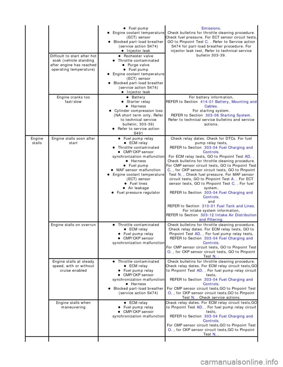
Fue
l pump
Engine coolan
t temperature
(ECT) sensor
Blocked part-load breather (
service action S474)
Injec
tor leak
Emiss
ions
.
Check bull
etins for throttle cleaning procedure.
Check fuel pressure. For ECT sensor circuit tests,
GO to Pinpoint Test C.
. Refer to Servi
ce action
S474 for part-load breather procedure. For
injector leak test, Refer to technical service bulletin 303-39.
D
ifficult to start after hot
soak (vehicle standing
after engine has reached operating temperature)
Roc
hester valve
Thr
ottle contaminated
Purge
valve
Fue
l pump
Engine coolan
t temperature
(ECT) sensor
Blocked part-load breather (
service action S474)
Injec
tor leak
Engine cranks too
fa
st/slow
Batt
ery
Starter relay Harness Cyl
inder compression loss
(NA short term only. Refer to technical service bulletin; 303-39)
R
efer to service action
S491
F
or battery information,
REFER to Section 414
-0
1 Battery, Mounting and
Cables.
F
or starting system.
REFER to Section 303
-06 Sta
rting System
.
R
efer to technical servic
e bulletins and service
actions.
Engine
stalls
Engine st
alls soon after
start
F
uel pump relay
ECM relay Thr
ottle contaminated
CMP/CKP sen
sor
synchronization malfunction
Harness Fue
l pump
MAF
sensor malfunction
Engine coolan
t temperature
(ECT) sensor
Fue
l lines
Air leakage
F
uel pressure regulator
Check r
elay dates. Chec
k for DTCs. For fuel
pump relay tests,
REFER to Section 303
-0
4 Fuel Charging and
Controls.
F
or ECM relay tests, GO to Pinpoint Test
AD.
.
Check bull
etins for throttle cleaning procedure.
For CMP sensor circuit test s, GO to Pinpoint Test
C.
, for
CKP sensor circuit tests, GO to Pinpoint
Test N.
. Check fuel
pressure. For MAF sensor
circuit tests, GO to Pinpoint Test A.
. For EC
T
sensor tests, GO to Pinpoint Test C.
. F
or fuel
system,
REFER to Section 303
-0
4 Fuel Charging and
Controls.
and
REF
ER to Section 310
-0
1 Fuel Tank and Lines
. F
or intake system information,
REFER to Section 303
-1
2 Intake Air Distribution
and F
iltering
.
Engine
stalls on overrun
Thr
ottle contaminated
ECM relay F
uel pump relay
CMP/CKP sen
sor
synchronization malfunction
Check bull
etins for throttle cleaning procedure.
Check relay dates. For ECM relay tests, GO to Pinpoint Test AD.
. F
or fuel pump relay tests,
REFER to Section 303
-0
4 Fuel Charging and
Controls.
F
or CMP sensor circuit test
s, GO to Pinpoint Test
O.
, for
CKP sensor circuit tests, GO to Pinpoint
Test N.
.
E
ngine stalls at steady
speed, with or without cruise enabled
Thr
ottle contaminated
ECM relay F
uel pump relay
CMP/CKP sen
sor
synchronization malfunction
Harness Blocked part-load breather
(
service action S474)
Check bull
etins for throttle cleaning procedure.
Check relay dates. For EC M relay circuit tests,GO
to Pinpoint Test AD.
. F
or fuel pump relay circuit
tests,
REFER to Section 303
-0
4 Fuel Charging and
Controls.
F
or CMP sensor circuit test
s,GO to Pinpoint Test
O.
, for
CKP sensor circuit tests,GO to Pinpoint
Test N.
. Che
ck service actions.
Engine st
alls when
maneuvering
ECM relay F
uel pump relay
CMP/CKP sen
sor
synchronization malfunction
Check r
elay dates. For EC
M relay circuit tests,GO
to Pinpoint Test AD.
. F
or fuel pump relay circuit
tests,
REFER to Section 303
-0
4 Fuel Charging and
Controls.
F
or CMP sensor circuit test
s,GO to Pinpoint Test
O.
, for
CKP sensor circuit tests,GO to Pinpoint
Test N.
.
Page 1204 of 2490
op
en circuit
ECM ground circuit faul
t (relay coil
drive)
P1235Vacuu m
switching valve (VSV) 1
circuit range/ performance
(mechanical guard position)
Vac u
um leak/blockage between the
throttle elbow and the throttle
vacuum actuator
Vacuu m
actuator failure
Mechanica
l
guard actuator
seized/spring broken
Carr y out mechanical checks
for
vacuum leak/blockag e, failed vacuum
actuator, and broken /siezed actuator
spring.
P1236Vacuu m
switching valve (VSV) 1
(vacuum) circuit failure
VSV 1 disconne cted
VSV 1 to ECM drive circu
i
t high
resistance, open circuit or short
circuit
VSV 1 powe r supply open
circuit
VSV 1 failu
r
e
For VSV tests,
REF
ER to Section 310
-03
Sp
eed
Control.
P1237Vacuu
m
switching valve (VSV) 2
(atmosphere) circuit failure
VSV 2 disconne cted
VSV 2 to ECM drive circu
i
t high
resistance, open circuit or short
circuit
VSV 2 power supply open
circuit
VSV 2 failu
r
e
For VSV tests,
REF
ER to Section 310
-03
Sp
eed
Control.
P1238Vacuu
m
switching valve (VSV) 3
(release) circuit failure
VSV 3 disconne cted
VSV 3 to ECM drive circu
i
t high
resistance, open circuit or short
circuit
VSV 3 powe r supply open
circuit
VSV 3 failu
r
e
For VSV tests,
REF
ER to Section 310
-03
Sp
eed
Control.
P1240Sensor r
e
fere
nce voltage
malfunction (throttle sensors, fuel
tank pressure se nsor) (ECM pins
EM10-21; EM11-8)
ECM t o
sensors reference voltage
short circuit to ground, short circuit
to high voltage, op en circuit, high
resistance
TP sensor , pedal position and
mechan
ical guard sensor(s), fuel
tank pressure sens or failure(s)
Fo
r sensor reference voltage circuit
tests,GO to Pinpoint Test V.
.
P1241Sensor re
ferenc
e voltage low
(throttle sensors, fuel tank
pressure sensor) (ECM pins EM10-
21; EM11-8)
ECM t o
sensors reference voltage
short circuit to ground
TP sensor , APP
and mechanical
guard sensor(s), fuel tank pressure
sensor failure(s)
F o
r sensor reference voltage circuit
tests,GO to Pinpoint Test V.
.
P1242Sensor re
ferenc
e voltage high
(throttle sensors, fuel tank
pressure sensor) (ECM pins EM10-
21; EM11-8)
ECM t o
sensors reference voltage
circuit open circuit, high resistance,
short circuit to high voltage
TP sensor , APP
and mechanical
guard sensor(s), fuel tank pressure
sensor failure(s)
F o
r sensor reference voltage circuit
tests,GO to Pinpoint Test V.
.
P1243Sensor re
ference ground
malfunction (throttle sensors, fuel
tank pressure sensor, ECT sensor,
IAT sensor, IAT sensor 2) (ECM
pins EM10-20; EM11-12)
ECM t o
sensors reference ground
circuit open circuit, high resistance
Throttle sensors, fuel
tank pressure
sensor, ECT sensor, IAT sensor,
IAT sensor 2 failures
F o
r sensor reference ground circuit
tests,GO to Pinpoint Test W.
.
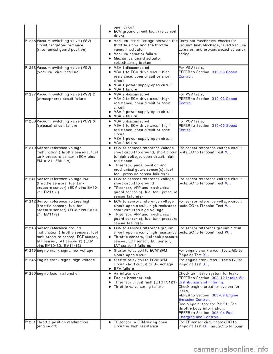
P1245Engine crank signal low voltage Starter relay coi
l to ECM/BPM
circuit open circuit
For en gin
e crank circuit tests,GO to
Pinpoint Test X.
.
P1246Engine crank signal high voltage Starter relay coi
l to ECM/BPM
circuit short circuit to B+ voltage
B P
M failure
For en
gin
e crank circuit tests,GO to
Pinpoint Test X.
.
P1250Engine load
malfunction
Air in
take leak
Engine breath
er leak
TP sens
or circuit fault (DTC P0121)
Throttle
valve spring failure
Check air i
ntake system for leaks,
REFER to Section 303
-12
Intake Air
Distribution and Filterin
g
.
Check engi
ne breather system for
leaks,
REFER to Section 303
-08 En
gine
Emissi
on Control.
Se e
pinpoint test for P0121. For
throttle body information,
REFER to Section 303
-04 Fu
el
Charging and Con
t
rols
.
P1251Thr
o
ttle position malfunction
(engine off)
TP sensor to ECM wiri
ng open
circuit or high resistance
F o
r TP sensor circ
uit tests,GO to
Pinpoint Test D.
, andGO to Pinpoint
Page 1228 of 2490
Is the res
istance greater than 5 ohms?
Yes GO to W10
.
No
GO to W11
.
W10 :
CHECK THE IAT SENSOR REFERENCE
GROUND CIRCUIT FOR HIGH RESISTANCE
Di
sconnect the ECM electrical connectors, EM10 and EM11.
1
Meas
ure t
he resistance between PI35,
pin 04 (BG) and EM10, pin 20 (BG).
2
Measure t
he resistance between PI35,
pin 04 (BG) and EM11, pin 12 (BG).
3
Is either resistance greater
than 5 ohms?
Yes REPAIR the high resistance circuit. For additional information, refer to the wiring diagrams. CLEAR the
DTC. TEST the system for normal operation.
No GO to W11
.
W11 :
CHECK THE SENSOR REFERENCE GROUND AT THE IAT SENSOR #2
Re
conn
ect the ECM electrical connectors, EM10 and EM11.
1
Di
sc
onnect the IAT sensor 2 electrical connector, PI03.
2
Meas
ure t
he resistance between PI03, pin 01 (BG) and GROUND.
3
Is th
e res
istance greater than 5 ohms?
Yes GO to W12
.
No
CHECK
for DTCs associated with TP sensor, APP/
mechanical guard sensor, FTP sensor, ECT sensor,
IAT sensor, or IAT sensor 2. INST ALL a new sensor as indicated by the DTC. CLEAR the DTC. TEST
the system for normal operation.
W12 :
CHECK THE IAT SENSOR #2 REFERENC
E GROUND CIRCUIT FOR HIGH RESISTANCE
Di
sconnect the ECM electrical connectors, EM10 and EM11.
1
Meas
ure t
he resistance between PI03,
pin 01 (BG) and EM10, pin 20 (BG).
2
Measure t
he resistance between PI03,
pin 01 (BG) and EM11, pin 12 (BG).
3
Is either resistance greater
than 5 ohms?
Yes REPAIR the high resistance circuit. For additional information, refer to the wiring diagrams. CLEAR the
DTC. TEST the system for normal operation.
No CHECK for DTCs associated with TPS, APP/mechanical guard sensor, FTP sensor, ECT sensor, IAT
sensor, or IAT sensor #2. INSTALL a new sensor as indicated by the DTC. CLEAR the DTC. TEST the
system for normal operation.
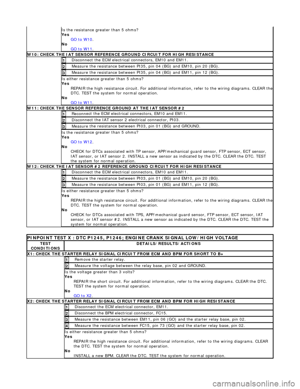
PINPO
INT TEST X : DTC P1245, P1246; ENGINE CRANK SIGNAL LOW/HIGH VOLTAGE
TE
S
T
CONDITIONS
D E
TAILS/RESULTS/ACTIONS
X
1
: CHECK THE STARTER RELAY SIGNAL CIRC
UIT FROM ECM AND BPM FOR SHORT TO B+
Re
move the starter relay.
1
Meas
ure t
he voltage between the
relay base, pin 02 and GROUND.
2
Is the volt
age greater than 3 volts?
Yes REPAIR the short circuit. For addi tional information, refer to the wiring diagrams. CLEAR the DTC.
TEST the system for normal operation.
No GO to X2
.
X2
: CHECK THE STARTER RELAY SIGNAL CIRCUI
T FROM ECM AND BPM FOR HIGH RESISTANCE
Di
sconnect the ECM electrical connector, EM11.
1
Disc
onne
ct the BPM electrical connector, FC15.
2
Meas
ure t
he resistance between EM11, pin 06
(GO) and the starter relay base, pin 02.
3
Measure t
he resistance between FC15, pin 73
(GO) and the starter relay base, pin 02.
4
Is either resistance greater
than 5 ohms?
Yes REPAIR the high resistance circui t. For additional information, refer to the wiring diagrams. CLEAR
the DTC. TEST the system for normal operation.
No INSTALL a new BPM. CLEAR the DTC. TEST the system for normal operation.
Page 1453 of 2490
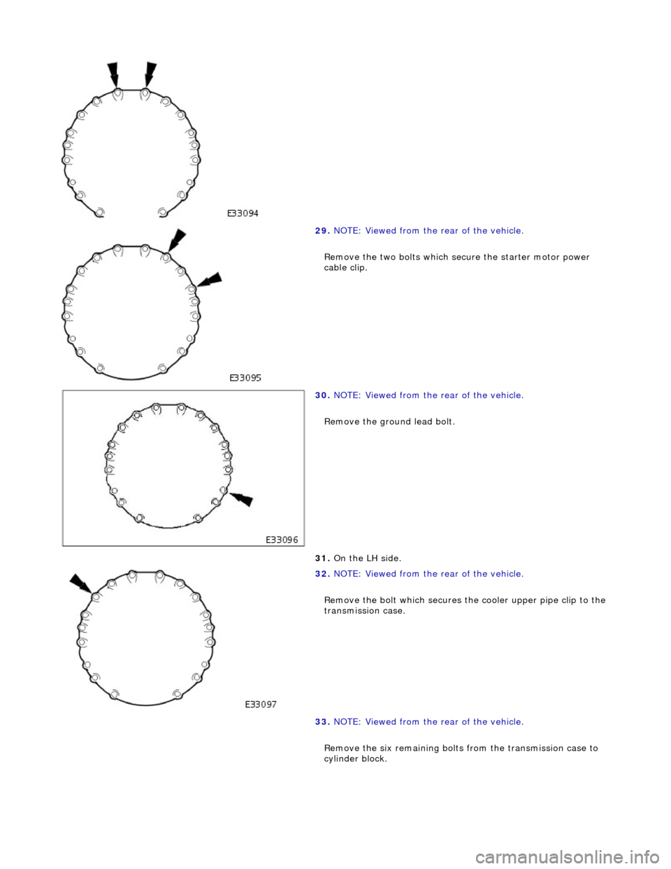
29. NOTE: Viewed from the rear of the vehicle.
Remove the two bolts which se cure the starter motor power
cable clip.
30. NOTE: Viewed from the rear of the vehicle.
Remove the ground lead bolt.
31. On the LH side.
32. NOTE: Viewed from the rear of the vehicle.
Remove the bolt which secures the cooler upper pipe clip to the
transmission case.
33. NOTE: Viewed from the rear of the vehicle.
Remove the six remaining bolts from the transmission case to
cylinder block.
Page 1459 of 2490

6. Fit the mounting bracket for th e front muffler. Tighten the two
bolts to the specified torque figure.
7. Secure the transmission to the engine.
Loosely assemble - Cooler pipe clip bolt.
Loosely assemble - Ground lead bolt.
Loosely assemble - Starter cable clips, two bolts.
Loosely assemble - Catalyst bracket bolts, two each side.
Loosely assemble - Rema ining eight bolts.
Refer to the illustration - tighten in sequence 1,2,3,4 then
in any order.
8. Secure the torque converter to the engine.
1. Fit, but do not tighten, the three bolts which secure the torque converter to the drive plate.
Prevent crankshaft rotation and tighten ALL converter
bolts to the specified torque figure.
2. Fit the blanking plug to the cylinder block access aperture.
9. Secure the oil cooler pipes.
Fit new Dowty washers to each union. Connect the upper
and lower cooler pipes.
Tighten to the specified torque figure.
Page 1876 of 2490
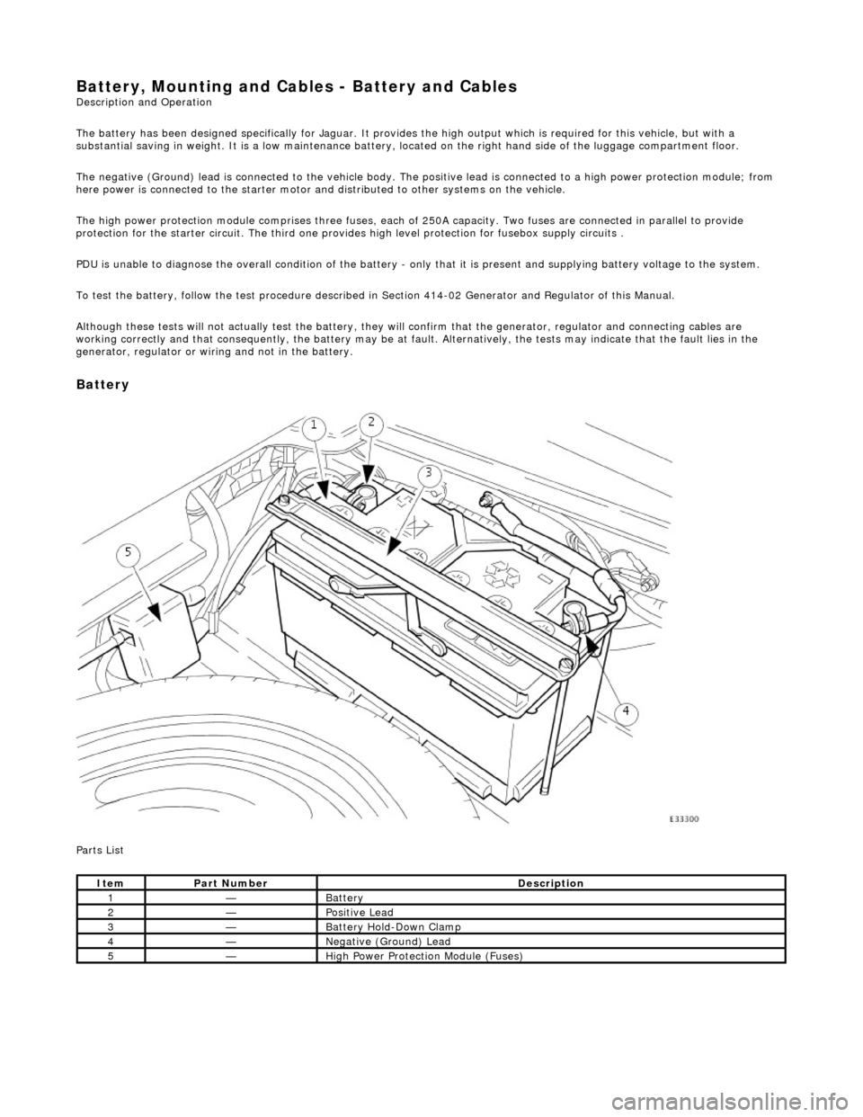
Battery, Mounting and Cables - Battery and Cables Description and Operation
The battery has been designed specifically for Jaguar. It provides the high output which is required for this vehicle, but with a
substantial saving in weight. It is a low maintenance battery, located on the right ha nd side of the luggage compartment floor.
The negative (Ground) lead is connected to the vehicle body. The positive lead is connected to a high power protection module; from
here power is connected to the starter motor an d distributed to other systems on the vehicle.
The high power protection module comprises three fuses, each of 250A capacity. Two fuses are connected in parallel to provide
protection for the starter circuit. Th e third one provides high level protection for fusebox supply circuits .
PDU is unable to diagnose the overall condition of the battery - only that it is present and supplying battery voltage to the system.
To test the battery, follow the test procedure described in Section 414-02 Generator and Regulator of this Manual.
Although these tests will not actually test the battery, they will confirm that the generator, regulator and connecting cables are
working correctly and that conseq uently, the battery may be at fault. Alternatively, the tests may indicate that the fault lies in the
generator, regulator or wiring and not in the battery.
Battery
Parts List
ItemPart NumberDescription
1—Battery
2—Positive Lead
3—Battery Hold-Down Clamp
4—Negative (Ground) Lead
5—High Power Protection Module (Fuses)
Page 1883 of 2490
Belt tension is achieved by an automatic tensioner; neither the belt nor the tensioner require service apart from checking
the belt wear indicators at each normal service interval.
The minimum service life of the drive belt is 100,000 miles.
Never apply oil to the belt or to the belt tensioner.
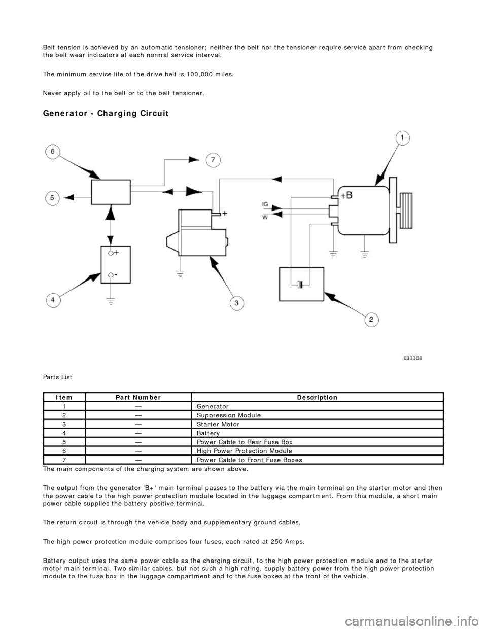
Generator - Charging Circuit
Parts List
The main components of the charging system are shown above.
The output from the generator 'B+' main te rminal passes to the battery via the main terminal on the starter motor and then
the power cable to the high power protection module located in the luggage compartment. From this module, a short main
power cable supplies the ba ttery positive terminal.
The return circuit is through the vehicle body and supplementary ground cables.
The high power protection mo dule comprises four fuses, each rated at 250 Amps.
Battery output uses the same power cable as the charging circ uit, to the high power protection module and to the starter
motor main terminal. Two similar cables, but not such a high rating, supply battery power from the high power protection
module to the fuse box in the luggage compartment an d to the fuse boxes at the front of the vehicle.
ItemPart NumberDescription
1—Generator
2—Suppression Module
3—Starter Motor
4—Battery
5—Power Cable to Rear Fuse Box
6—High Power Protection Module
7—Power Cable to Front Fuse Boxes
Page 1889 of 2490
CAUTION: The engine must not be running when multiplugs are connected or disconnected.
Check that the main B+ terminal is clean and tight.
Check that the IG terminal is clean and ma king good contact; if this connection is faulty, the generator will never function
correctly.
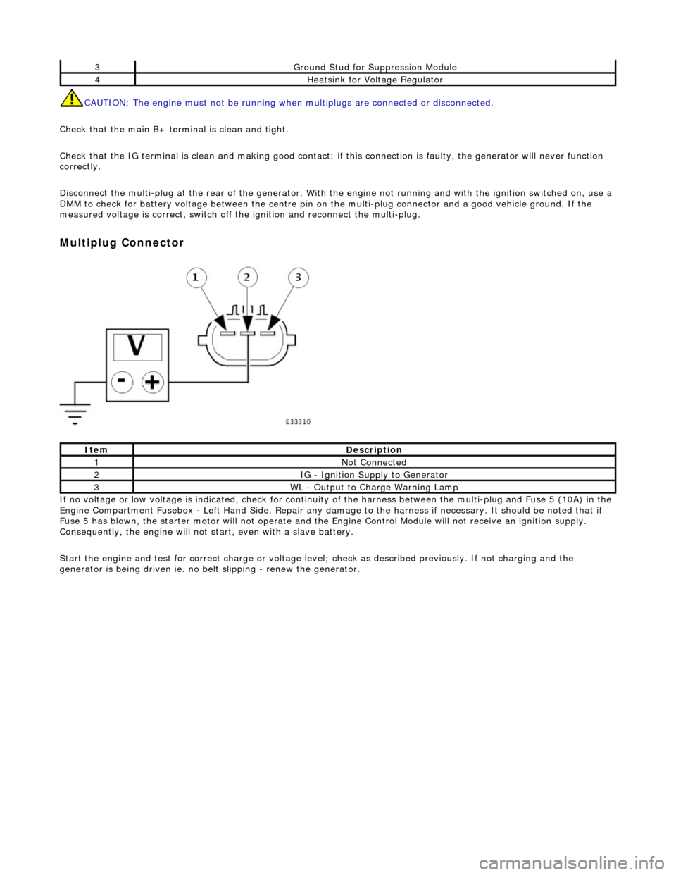
Disconnect the multi-plug at th e rear of the generator. With the engine not running and with the ignition switched on, use a
DMM to check for battery voltage between the centre pin on the multi-plug connector and a good vehicle ground. If the
measured voltage is correct, switch off the ignition and reconnect the multi-plug.
Multiplug Connector
If no voltage or low voltage is indicated, check for continuity of the harness between the multi-plug and Fuse 5 (10A) in the
Engine Compartment Fusebox - Left Hand Si de. Repair any damage to the harness if necessary. It should be noted that if
Fuse 5 has blown, the starter motor will not operate and the Engine Control Module will not receive an ignition supply.
Consequently, the engine will not st art, even with a slave battery.
Start the engine and test for correct ch arge or voltage level; check as described previously. If not charging and the
generator is being driven ie. no be lt slipping - renew the generator.
3Ground Stud for Suppression Module
4Heatsink for Voltage Regulator
ItemDescription
1Not Connected
2IG - Ignition Supply to Generator
3WL - Output to Charge Warning Lamp