1998 JAGUAR X308 FRONT DOOR PANEL
[x] Cancel search: FRONT DOOR PANELPage 2075 of 2490
Installation
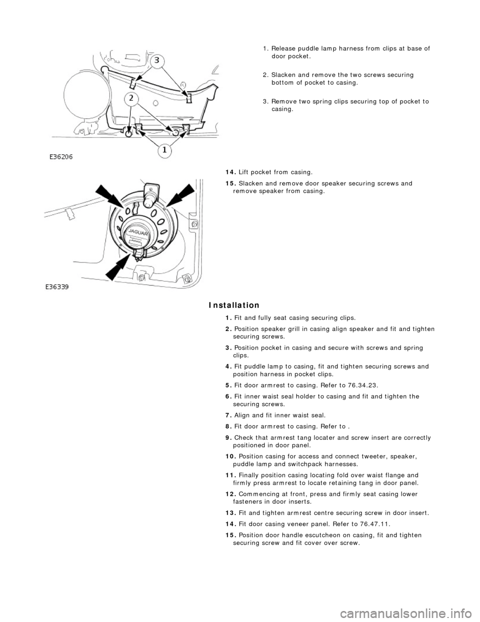
1. Release puddle lamp harness from clips at base of door pocket.
2. Slacken and remove th e two screws securing
bottom of pocket to casing.
3. Remove two spring clips securing top of pocket to casing.
14. Lift pocket from casing.
15. Slacken and remove door sp eaker securing screws and
remove speaker from casing.
1. Fit and fully seat casing securing clips.
2. Position speaker grill in casing align speaker and fit and tighten
securing screws.
3. Position pocket in casing and secure with screws and spring
clips.
4. Fit puddle lamp to casing, fit and tighten securing screws and
position harness in pocket clips.
5. Fit door armrest to casing. Refer to 76.34.23.
6. Fit inner waist seal holder to casing and fit and tighten the
securing screws.
7. Align and fit inner waist seal.
8. Fit door armrest to casing. Refer to .
9. Check that armrest tang locater and screw insert are correctly
positioned in door panel.
10. Position casing for access and connect tweeter, speaker,
puddle lamp and switchpack harnesses.
11. Finally position casing locating fold over waist flange and
firmly press armrest to locate retaining tang in door panel.
12. Commencing at front , press and firmly seat casing lower
fasteners in door inserts.
13. Fit and tighten armrest centre se curing screw in door insert.
14. Fit door casing veneer panel. Refer to 76.47.11.
15. Position door handle escutche on on casing, fit and tighten
securing screw and fit cover over screw.
Page 2090 of 2490
Interior Trim and Ornamentation - Rear Door Trim Panel Finish Panel
Removal and Installation
Removal
Installation
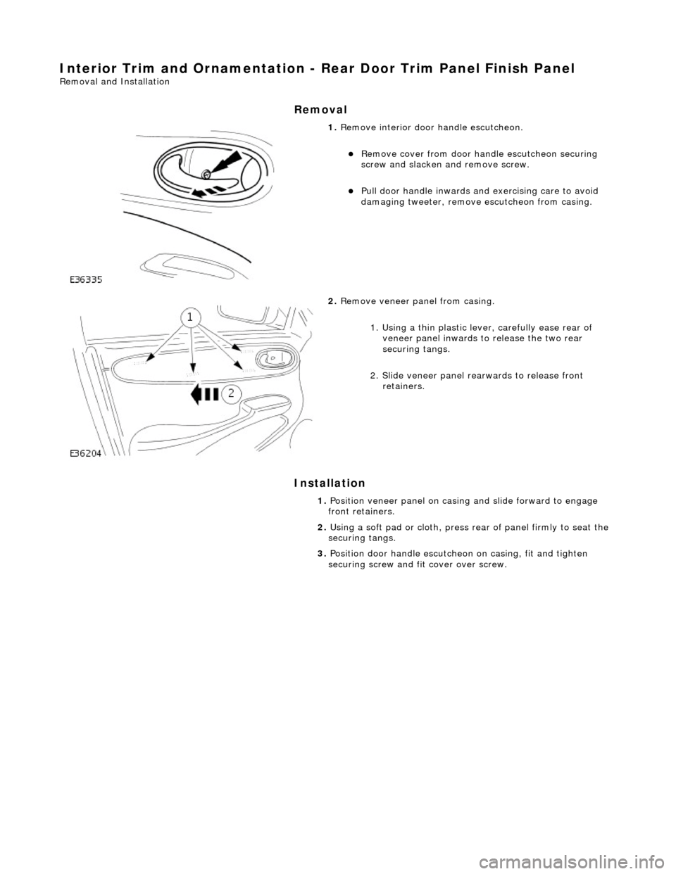
1. Remove interior door handle escutcheon.
Remove cover from door ha ndle escutcheon securing
screw and slacken and remove screw.
Pull door handle inwards and exercising care to avoid
damaging tweeter, remove escutcheon from casing.
2. Remove veneer panel from casing.
1. Using a thin plastic leve r, carefully ease rear of
veneer panel inwards to release the two rear
securing tangs.
2. Slide veneer panel re arwards to release front
retainers.
1. Position veneer panel on casing and slide forward to engage
front retainers.
2. Using a soft pad or cloth, press re ar of panel firmly to seat the
securing tangs.
3. Position door handle escutche on on casing, fit and tighten
securing screw and fit cover over screw.
Page 2094 of 2490
primary water shedder is undamag
ed and correctly attached to
door inner panel.
Align and fit inner waist seal.
8. Check that armrest tang locater and screw insert are correctly
positioned in door panel.
9. Position casing for access and connect speaker, puddle lamp
and switchpack harnesses.
10. Finally position casing locating fold over waist flange and
firmly press armrest to locate retaining tang in door panel.
11. Commencing at front , press and firmly seat casing lower
fasteners in door inserts
12. Fit and tighten armrest centre se curing screw in door insert.
13. Fit door veneer panel. Refer to 76.47.12.
14. Position door handle escutche on on casing, fit and tighten
securing screw and fit cover over screw.
Page 2190 of 2490
Glass, Frames and Mechanisms - Front Door Window Control Switch
Removal and Installation
Removal
Installation
1.
Remove casing/armrest asse mbly from door. Refer to
76.34.01.
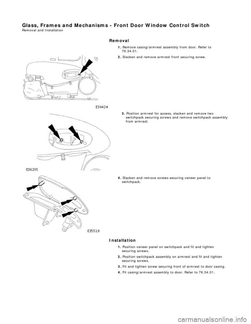
2. Slacken and remove armres t front securing screw.
3. Position armrest for access, slacken and remove two
switchpack securing screws and remove switchpack assembly from armrest.
4. Slacken and remove screws securing veneer panel to
switchpack.
1. Position veneer panel on sw itchpack and fit and tighten
securing screws.
2. Position switchpack assembly on armrest and fit and tighten
securing screws.
3. Fit and tighten screw securing fr ont of armrest to door casing.
4. Fit casing/armrest assembly to door. Refer to 76.34.01.
Page 2273 of 2490
Handles, Locks, Latches and Entry Systems - Handles, Locks, Latches and
Entry Systems
Description and Operation
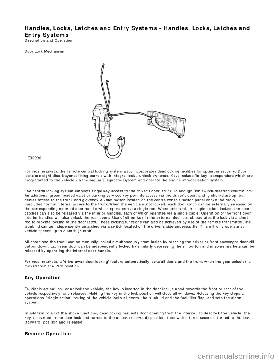
Door Lock Mechanism
For most markets, the remote central locking system also, in corporates deadlocking facilities for optimum security. Door
locks are eight disc, bayonet fixing barrels with integral lock / unlock switches. Keys include 'in-key' transponders which are
programmed to the vehicle via the Jaguar Diagnostic Sy stem and operate the engine immobilisation system.
The central locking system employs single key access to the driv er's door, trunk lid and ignition switch/steering column lock.
An additional green headed valet or park ing services key permits access via the driver's door, and ignition/start-up, but
denies access to the trunk and glovebox.A valet switch located on the centre console switch panel above the radio,
precludes normal internal access to the trunk.When the vehicle is not locked, each door catch can be externally released by
the corresponding external door handle which operates via a si ngle rod. When unlocked, or 'single action' locked, the door
catches can also be released via the interior handles, each of which operates via a single cable. Operation of the front door
interior handles will also unlock the rear doors. Use of either key in the external door barrel, operates the lock via a short
rod to provide locking of the door latch. These locking functions can also be achieved by use of the remote transmitter.The
trunk lid can be independently unlatched via a switch located on the driver's side underscuttle. This will only operate at
vehicle speeds up to 8 km/h (5 mph).
All doors and the trunk can be manually lock ed simultaneously from inside by pressing the driver or front passenger door sill
button down. Each rear door can be independently locked by si milarly depressing the sill button and in some markets can be released by operating the internal door handle.
For most markets, a 'drive-away door locking' feature automati cally locks all doors and the trunk when the gear selector is
moved from the Park position.
Key Operation
To 'single action' lock or unlock the vehicle, the key is inserted in the door lock , turned towards the front or rear of the
vehicle respectively, and released. Holding the key in the lock position will close all windows. Releasing the key stops all
operations. 'single action' locking of the vehicle locks all doors, the trunk lid and the fuel filler flap, and sets the alarm
system.
In addition to all of the above functions, deadlocking prevents door opening from th e interior. To deadlock the vehicle, the
key is inserted in the door lock and turned to the unlock (rearw ard) position, then within three seconds, turned to the lock
(forward) position and released.
Remote Operation
Page 2386 of 2490
Body Structure
Introduction
The standard wheelbase Jaguar sedan has a unit construction monocoque body structure with bolt-on front fenders and
welded rear fenders. The doors feature lif t-off hinges and welded drop-glass frames.
Constructional Steel Classification
BODY ALIGNMENT
The Body Dimensions Plan, and Body Dimensions Side View, provide specified BIW dimensions to facilitate damage
assessment and location of replacemen t parts. These dimensions must be strictly applied when used for damage
assessment, component location or post repair verification.
• NOTE: The right-hand side is always looking towards the front, from the rear of the vehicle.
The nominated plan view master datums are on the right-hand side of the body with the left-hand datums dimensioned
from them. Right-hand datums must therefore be known to be correct before any other cross-car dimensions are checked.
Datum location, Example
The Front Master Datum (front crossmember rear mounting at the inner face of the main floor RH longitudinal) is nominally
359,5mm to the right-hand side of the body center line. The LH side fron t datum is measured 717,0 / 721,0mm from the
RH. Refer to the Body Dimensions Plan.
Expressed as a true posi tion in three planes, the front master datum is:
Standard Wheelbase Bo dy Dimensions-Plan
MaterialApplication
High strength low alloy
(HLSA).Impact prone areas, ie. seat frame and bumper mountings.
Double sided zinc plated mild steel.Exterior body panels subject to severe cond itions such as stone chipping and weather
exposure (excluding roof panel).
Boron steelDoor intrusion beams
Mild steel.Internal brackets, fill ets and strengtheners.
DatumLocationPosition
Front Master Datum
PlanCentre line of the front crossmember rear mounting, at the main floor RH
longitudinalX
300,0
Y 359,5 Z -50,0
Page 2417 of 2490
Panels centered between two adjacent panels must have equal gaps on either side. For exceptions to this, refer to the
appropriate specification. Gaps between ad jacent panels or components must not expose harnesses, labels, brackets or
visually poor joint or assembly conditions.
• NOTE: Sliding roof panel clearances are specified without the edge seal installed.
Areas of particular concern are, fuel filler flap, trunk lid to fenders and saddle panels, hood to fenders, grill and headlamps,
sliding roof to main roof panel, door gaps at fenders, B\C posts, roof drip rail an d rocker panel, and bumper cover to fenders
and cross car assemblies
Alignment
Panels must be correctly profiled to maintain cosmetic appearance, and ensure co rrect seating of seals with minimal wind
noise. Areas of particular concern are hood to fenders, trunk lid to fenders and saddle panels, doors to apertures, doors to
fenders and adjacent doors and relationship of the sliding roof panel leading and trailing edges to the main roof panel.
Exterior Fitments
Bezels, trims and lamps must be concentric with apertu res and have equal clearances with adjacent panels.
Areas of particular concern are headlamp to hood, fender and trim panel, exhaust tailpipe trim to bumper cover cut-out,
rear lamp assembly to trunk lid, fender and bumper cover trim, and side feature lines including body side mouldings, fender
to door and door to door.
Exterior Clearances and Alignments-Front