Page 469 of 2490
Buzz (E
lectrical)
A
different steering buzz can be caused by
pulse width modulated (PWM) electric actuators used in variable assist steering
systems. This buzz is felt by turning the ignition key to run without starting the engine and holding onto the steering wheel.
In extreme cases, the buzz can be felt with the engine running also.
Column/Steering Wheel
Shake
Column shake is a low f
requenc
y vertical vibration excited by primary engine vibrations.
Nibble (Shimm
y)
Steeri
ng nibble is a rotary oscillation or
vibration of the steering wheel, which can be excited at a specific vehicle speed.
Nibble is driven by wheel and tire imbalance exciting a suspensi on recession mode, which then translates into steering gear
travel and finally steering wheel nibble.
Shudder (Judd
er)
Shudder i
s a low frequency oscillation of th
e entire steering system (tire, wheels, st eering gear and linkage, etc.) when the
vehicle is steered during static-park or at low sp eeds. Shudder is very dependent on road surface.
Torque Ri
pple
Torque rippl
e is a concern with Electric Power Steering (EPS) sy
stems. Torque ripple is most evident at static-park steering
the wheel very slowly from lock to lock. Torque ripple is primarily caused by motor commutation.
Torque/Veloc
ity Variation
(Phasing/Effort Cycling)
Steeri
ng wheel torque variation oc
curring twice in one revolution is normally as a result of problems with the lower steering
column (intermediate shaft), but foul cond itions generally result in either constant stiffnes s or single point stiffness.
Depending upon the orientation of the joints, the steering can fe el asymmetric (torque falling off in one direction and rising
in the other) or else it can simply have pronounced peaks and troughs as the steering moves from lock to lock.
Wheel Fight
(Kick Back)
W
heel fight is excess feedback of sudden road forces through th
e steering system and back to the driver. It is evaluated at
all vehicle speeds over cobblestones, rough roads, and potholes . The tires, wheels, and suspension generate forces into the
steering systems. Steering friction, hydraulic damping, hydr aulic compliance, mechanical compliance, steering ratio, and
assist gain all affect how much is transmitted to the driver.
Stee
ring Linkage
CAUTI
ON: Steering gear boots must be
handled carefully to avoid damage. Use new clamps when installing steering
gear boots.
Inspect the boots for cuts, deterioration, tw isting or distortion. Check the steering gear boots to make sure they are tight.
Install new boots or clamps as necessary.
• NOTE: The following steps must be carried out with assistance.
1. 1. With the wheels in the straight ahead po sition, gently turn the steering wheel to the left and the right to check for
free play.
2. 2. Free play should be between 0 and 6 mm (0 and 0.24 in) at the steering wheel rim. If the free play exceeds this
limit, either the ball joints are worn, the lower steering column joints are worn or the backlash of the steering gear
is excessive.
Page 471 of 2490
Stee
ring System - General Informatio
n - Power Steering System Filling
and Bleeding
Gen
eral Procedures
Fluid Level Indica
tor
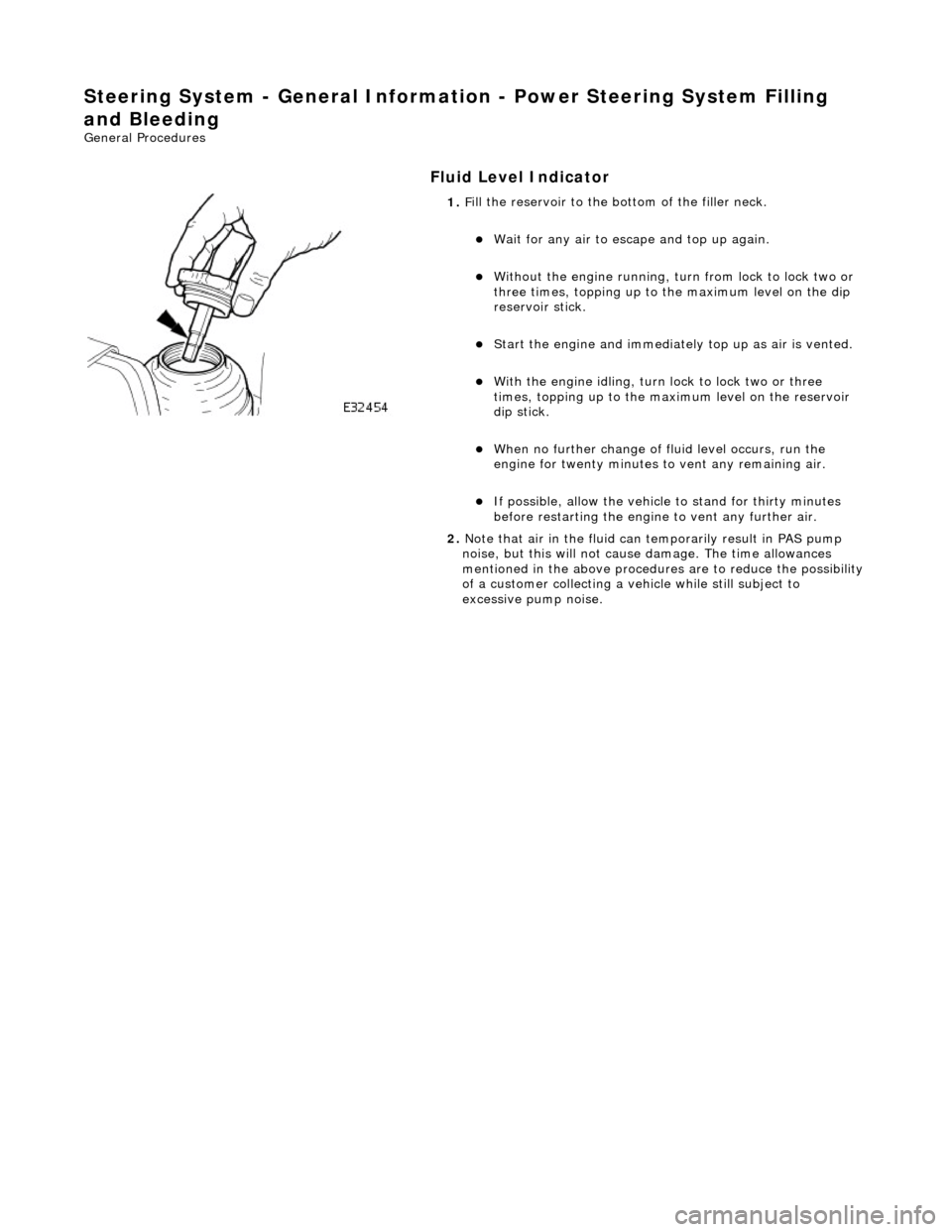
1.
F
ill the reservoir to the bo
ttom of the filler neck.
W
ait for any air to escape and top up again.
W
ithout the engine running, tu
rn from lock to lock two or
three times, topping up to the maximum level on the dip
reservoir stick.
St
art the engine and
immediately top up as air is vented.
W
ith the engine idling, turn
lock to lock two or three
times, topping up to the ma ximum level on the reservoir
dip stick.
W
hen no further change of
fluid level occurs, run the
engine for twenty minutes to vent any remaining air.
If po
ssible, allow the vehicle
to stand for thirty minutes
before restarting the engine to vent any further air.
2. Note that air in the fluid can temporarily result in PAS pump
noise, but this will not cause damage. The time allowances
mentioned in the above procedures are to reduce the possibility
of a customer collecting a vehicle while still subject to
excessive pump noise.
Page 520 of 2490
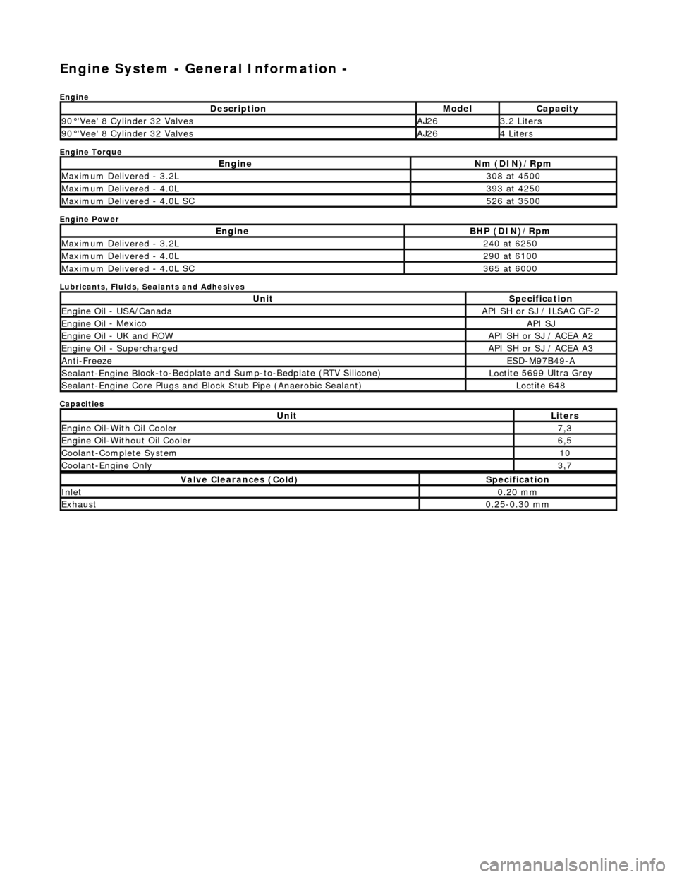
Engine System - General Inform
ation -
Eng
ine
Engine Torque
Engine Power
Lubricants, Fluids, Sealants and Adhesives
Capacities
Descr
iption
Mode
l
Capaci
ty
90
°'Ve
e' 8 Cylinder 32 Valves
AJ263.
2 L
iters
90
°'Ve
e' 8 Cylinder 32 Valves
AJ264 Li
te
rs
EngineNm (D
I
N)/Rpm
M
a
ximum Delivered - 3.2L
3
08 at
4500
M
a
ximum Delivered - 4.0L
3
93 at
4250
M
a
ximum Delivered - 4.0L SC
5
26 at
3500
EngineBH
P (D
IN)/Rpm
M
a
ximum Delivered - 3.2L
2
40 at
6250
M
a
ximum Delivered - 4.0L
2
90 at
6100
M
a
ximum Delivered - 4.0L SC
3
65 at
6000
UnitS
p
ecification
Engine Oil
-
USA/Canada
API SH or SJ
/ ILSAC G
F-2
Engine
Oil
- Mexico
API SJ
Engine
Oil
- UK and ROW
API SH or SJ
/ ACEA A2
Engine Oil -
Supercharged
API SH or SJ
/ ACEA A3
Anti-Freez
e
ESD-M97B
49
-A
Sealant-Engine B
l
ock-to-Bedplate an
d Sump-to-Bedplate (RTV Silicone)
Loct
ite 5699 Ultra Grey
Sealant-Engine
C
ore Plugs and Bloc
k Stub Pipe (Anaerobic Sealant)
Loctite 648
UnitLit
ers
Engine
Oil-W
ith Oil Cooler
7,
3
Engine Oil-W i
thout Oil Cooler
6,
5
Cool ant
-Complete System
10
Coo
lan
t-Engine Only
3,
7
Val v
e Clearances (Cold)
S
p
ecification
Inlet0.
20
mm
Exhaus
t0.25
-0.30 mm
Page 521 of 2490
Engine System - General Infor
mation - Engine
Description an
d Operation
The AJ26 power unit is available in 3.2 L and 4.0 L versions, and comprises:
An eight cylinder 9
0 degree 'V' config
uration liquid cooled aluminium cylinder block incorporating 'Nikasil' plated
cylinder bores.
Pi
stons of open-ended skirt design, with
two compression and one oil control ring.
Two al
uminium cylinder heads, each
incorporating two camshafts.
F
our valves per cylinder.
Al
uminium valve lifters and top mounted shims.
Vari
able valve timing (VVT) of the inlet camshafts (4.0 L normally aspirated only).
Camshaft
covers manufactured from Vinylester.
Al
uminium timing cover which accommodat
es the crankshaft front oil seal.
Sin
gle row primary and secondary chains dr
ive the camshafts of each cylinder bank.
An alu
minium bed pl
ate, incorporating iron main bearing supports, which accomm odate the oil pump pick-up,
Page 633 of 2490
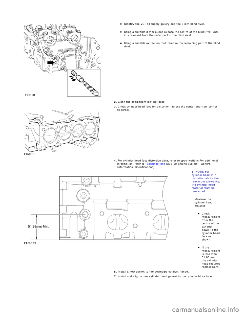
I
dentify the VCT oil supply gallery and the 8 mm blind rivet.
U
sing a suitable 3 mm punch release the centre of the blind rivet until
it is released from the outer part of the blind rivet.
U
sing a suitable extraction tool, remo
ve the remaining part of the blind
rivet.
2. Clean the component mating faces.
3.
Check cylinder head face for distortio
n, across the center and from corner
to corner.
4. For cylinder head face distortion data, refer to specifications.For additional
information, refer to: Specifications
(303
-00 Engine System - General
Information, Specifications).
5.
NOTE: For
cylinder head with
distortion above the
maximum allowance,
the cylinder head
material must be
measured.
Measure the
cylinder head
material.
Che
ck
measurement
from the
centre of the
exhaust
dowel to the
cylinder head
face as
shown.
If the
measurement
is less than
51.88 mm
the cylinder
head requires
replacement.
6.
Install a new gasket to the downpipe catalyst flange.
7. Install and align a new cylinder head gasket to the cylinder block face.
Page 641 of 2490
2.
Connect the multi-plug to the temperature sensor.
3. Expand and reposition the hose clip along the bypass hose.
43. Install the Inlet Manifold. Refer to Operation 30.15.01 in this Section. This
operation includes installing the throttle housing.
44. Install the engine front cover.For additional information, refer to: Engine
Front Cover (303-01 Engi
ne, In-vehicle Repair).
45. Move the engine compartment cover from the service position and connect
the gas struts.
46. Remove the paint protection sheets and close the cover.
47. Connect the battery and install th e battery cover.For additional
information, refer to: Battery Connect
(414
-01 Battery, Mounting and
Cables, General Procedures).
Page 858 of 2490
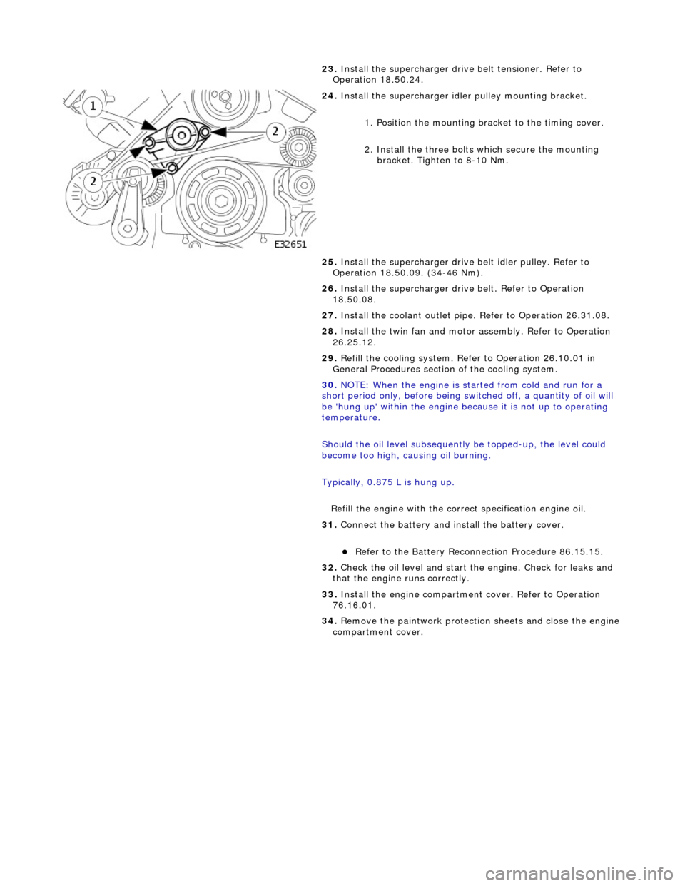
23.
Install the supercharger driv e belt tensioner. Refer to
Operation 18.50.24.
24. Install the supercharger idle r pulley mounting bracket.
1. Position the mounting bracket to the timing cover.
2. Install the three bolts which secure the mounting bracket. Tighten to 8-10 Nm.
25. Install the supercharger drive belt idler pulley. Refer to
Operation 18.50.09. (34-46 Nm).
26. Install the supercharger driv e belt. Refer to Operation
18.50.08.
27. Install the coolant outlet pipe. Refer to Operation 26.31.08.
28. Install the twin fan and motor assembly. Refer to Operation
26.25.12.
29. Refill the cooling system. Refer to Operation 26.10.01 in
General Procedures section of the cooling system.
30. NOTE: When the engine is star ted from cold and run for a
short period only, before being swit ched off, a quantity of oil will
be 'hung up' within the engine because it is not up to operating
temperature.
Should the oil level subsequently be topped-up, the level could
become too high, causing oil burning.
Typically, 0.875 L is hung up.
Refill the engine with the correct specification engine oil.
31. Connect the battery and in stall the battery cover.
Refer to the Battery Reconnection Procedure 86.15.15.
32. Check the oil level and start th e engine. Check for leaks and
that the engine runs correctly.
33. Install the engine compartmen t cover. Refer to Operation
76.16.01.
34. Remove the paintwork protection sheets and close the engine
compartment cover.
Page 923 of 2490
be 'hun
g up' within the engine because it is not up to operating
temperature.
Should the oil level subsequently be topped-up, the level could
become too high, causing oil burning.
Typically, 0.875L is hung up.
Refill the engine with the correct specification engine oil.
58. Refill the automatic transmission. Refer to Section 307-01A,
Operation 44.24. 02.
59. Refill and bleed the power stee ring system. Refer to Section
211-02 General Procedures.
60. Repressurise the air conditioni ng system. Refer to Operation
82.30.30 and note all Wa rnings and Cautions.
61
.
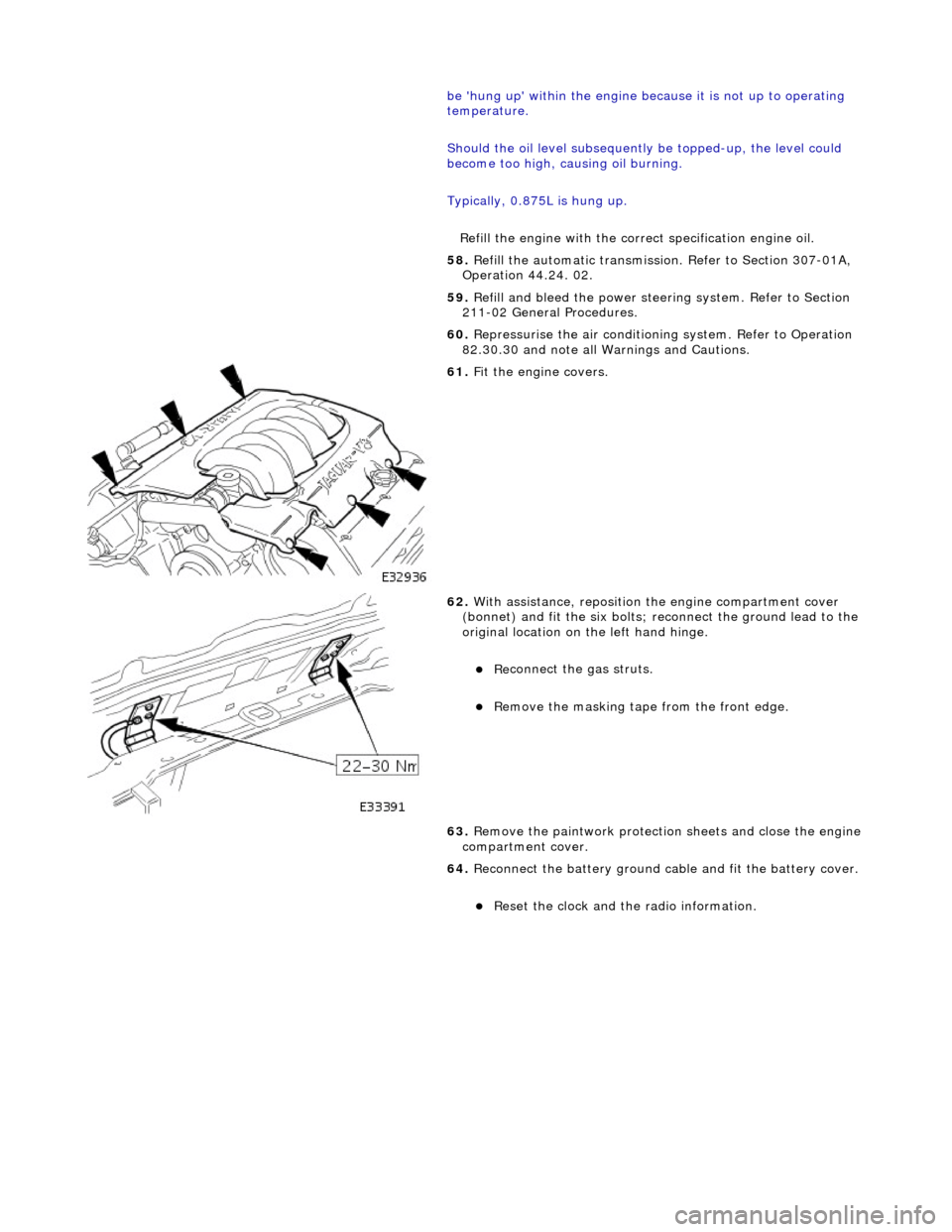
Fit the engine covers.
62
.
With assistance, reposition the engine compartment cover
(bonnet) and fit the si x bolts; reconnect the ground lead to the
original location on the left hand hinge.
Re
connect the gas struts.
R
emove the masking tape from the front edge.
63. Remove the paintwork protection sheets and close the engine
compartment cover.
64. Reconnect the battery ground cable and fit the battery cover.
Re
set the clock and the radio information.