1998 JAGUAR X308 Adaptive
[x] Cancel search: AdaptivePage 273 of 2490
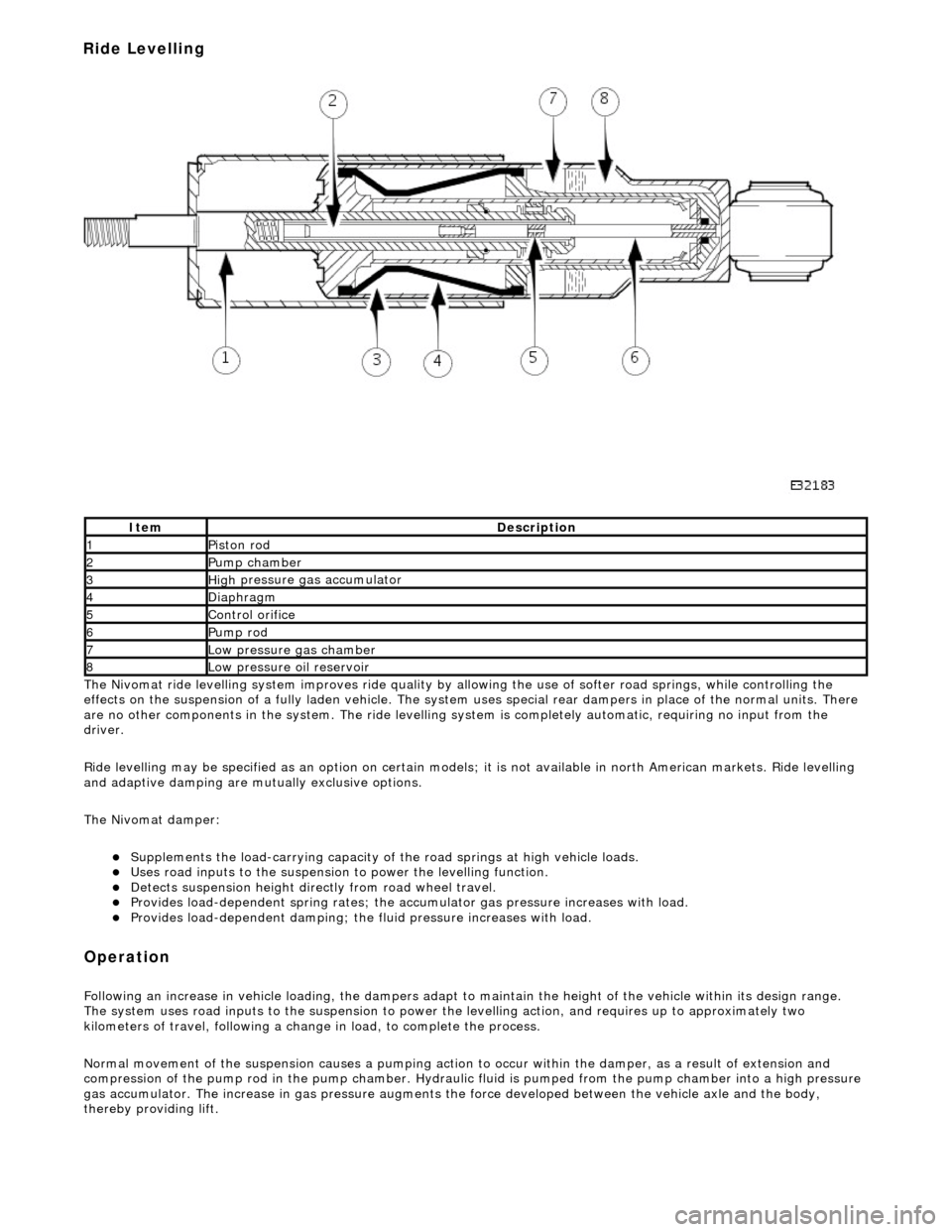
The
Nivomat ride levelling system improves ride quality by al
lowing the use of softer road springs, while controlling the
effects on the suspension of a fully laden vehicle. The system uses special rear dampers in place of the normal units. There
are no other components in th e system. The ride levelling system is comple tely automatic, requiring no input from the
driver.
Ride levelling may be specified as an opti on on certain models; it is not available in north American markets. Ride levelling
and adaptive damping are mu tually exclusive options.
The Nivomat damper:
Su
pplements the load-carrying capacity of th
e road springs at high vehicle loads.
Uses road inputs to the
suspension to power the levelling function.
De
tects suspension height dire
ctly from road wheel travel.
Provi
des load-dependent spring rates; the ac
cumulator gas pressure increases with load.
Pr
ovides load-dependent damping; the fluid pressure increases with load.
Op
eration
F
ollowing an increase in vehicle loading,
the dampers adapt to maintain the height of the vehicle within its design range.
The system uses road inputs to the suspension to power the levelling action, and requires up to approximately two
kilometers of travel, following a change in load, to complete the process.
Normal movement of the suspension caus es a pumping action to occur within the damper, as a result of extension and
compression of the pump rod in the pump chamber. Hydraulic fluid is pumped from the pump cham ber into a high pressure
gas accumulator. The increase in gas pressure augments the force developed between th e vehicle axle and the body,
thereby providing lift.
It
em
De
scription
1Pi
ston rod
2Pum
p chamber
3High
pressure
gas accumulator
4Diaphragm
5Co
ntrol orifice
6Pump rod
7Low pressure gas ch
amber
8Low pressure oil
reservoir
Ride Levelling
Page 274 of 2490

A c
ontrol orifice in the pump rod determines the levelling height. When the damper is compressed, this orifice is covered.
When the damper extends, the control orif ice is uncovered, pressure is released to the low pressure oil reservoir and the
system ceases to rise. When the vehicle is high after unloading, the opened control or ifice allows fluid to be returned to the
low pressure oil reservoir, and the suspensi on returns to its normal unladen height.
Ad
aptive Damping
•
NOTE: Items 2 and 5 are ALWAYS located
on the passenger side of the vehicle
Adaptive damping enhances vehicle handli ng by the use of special dampers which are controlled by a dedicated control
module.
Adaptive damping may be specified as an option on certai n models. Adaptive damping and ride levelling are mutually
exclusive options. The adaptive damping system is completely automatic, requiring no input from the driver.
A d
aptive Dampers
The adaptiv
e dampers:
Are inst
alled in place of the normal dampers.
Can be identified
by the cable and connector at the top of the unit.
Have two settings; fi
rm and so
ft.
It
e
m
De
scr
iption
1Dam
p
er, front right-hand
2Accel
e
rometer, lateral
3Accel
e
rometer,
front vertical
4D
a
mper, rear right-hand
5Adaptive dampin
g control module (A
DCM)
6Accel
e
rometer, rear vertical
7D
amper, rear l
eft-hand
8Dam
p
er, front left-hand
Page 278 of 2490
Vehicle Dynamic Suspension - Vehicle Dynamic Suspension
Diagn
osis and Testing
Refer to the PDU User Guide for details of diagnosing and testing the Adaptive Damping System. The PDU interrogates the
ADCM directly via the K and L lines to the J1962 diagnostic socket.
The PDU will give an indication of the integrity of each electron ic and electrical component. It will indicate, for example, that
the accelerometers are not broken, but not that they functionin g correctly when the vehicle is in motion. However, it is
exceptional for an accelero meter to function incorrectly in its dynamic mode if it is proved to be functioning when static.
Basic Checks
The accele
rometers have the following ch
aracteristics. At 0g (no movement of the body) each vertical accelerometer
outputs approximately 2.5V steady voltage; the lateral acce lerometer outputs approximately 1.5V. The voltage output due
to body movement is proportional to acceleration in the acceleration axis, up to approximately 4.5V and down to
approximately 0.5V.
Before changing any component, refer to the circuit diagrams and check the cont inuity of relevant harness circuits; in some
instances, the PDU will not different iate between a faulty component an d a damaged connection or wiring.
Check the following fuses:
En
gine compartment fuse
box, fuse F5 (10A).
Engine m
anagement fuse
box, fuse F1 (20A).
Check the following ADCM input/output lines:
Sy stem erro
r output from the ADCM
to the instrument cluster.
Vehicl
e speed output from the inst
rument cluster to the ADCM.
Foo
tbrake signal to the ADCM.
Check any relevant connections to confirm that the connection is electrically sound and that a terminal pin has not been
pushed back into the connector shell, ie. not ma king a connection to its mating pin or socket.
Page 522 of 2490

diverter val
ve (if fitted) and oil filter.
Main
bearings
which are grooved in the upper positions and plain in
the lower positions. They are manufactured from
aluminium / tin material.
A c
rankshaft with under
cuts and rolled fillets for extra strength.
Fracture
-split connecting rods in sintered-forged steel.
Brackets
bolted to the front of
the cylinder
block are used to mo unt all accessories.
A sin
gle, seven ribbed vee belt
drives the accessories.
An au
tomatic belt tensioner for the front accessory drive,
incorporating a wear indicator.
An advanced en
gine management system inco
rporating electronic throttle control.
The un
it meets the requirements of the CARB OBDII USA legislation.
Ancillary Systems
The an
ci
llary systems, driven by the engine, each have a
detailed Description and Operation along with Diagnostic
Procedures, and Removal and Installation instructions ; refer to the following sections of this manual:
Power Steeri
ng Pump - Section 211-02
Ai
r Conditioning Compressor - Sectio
n 412-03
Engine
C
ooling Pump - Section 303-03
Generator
- Sectio
n 414-02
The drive belt, idler pulley and automatic tensioner are described in Section 303-05.
The engine starting system is described in Section 303-06.
En
gine Management and Emission Control System
Engine Control Modu
le (ECM)
Engine
management and exhaust emissions are controlled by the ECM, which has the
following main functions:
Fu
el injection
Idle
s
peed
Ignition Ev
aporative loss system
Engine
cooling fans Clim
ate control compressor clutch demand
The microprocessor within the ECM receiv es signals from various sensors and other modules and uses a pre-determined
program to compute engine management functions.
Adaptive functions are incorporated in the ECM to cater for co ntinuous adjustments to its computations to suit prevailing
conditions. Because the system also controls emissions to suit all modes, neither CO levels nor idle speed require service
attention or adjustment, except if an error should occur.
On Board Diagnostics are controlled by the ECM with the continuous monitoring of incoming signals and the subsequent
verification against what the module expects to 'see'. Should a si gnal be incorrect or missing, the ECM will substitute a fixed
value to provide the 'limp home mode' and alert the driver of the problem. Fixed values may be adopted for:
Transmission oil
temperature
Mechanica
l
guar
d position
Throttle blade angle Camshaft position
Inta
k
e air temperature
Diagnostic trouble codes (DTC), including OBD II codes, are stored in the ECM memo ry and can be read by an appropriate
retrieval tool.
Should either the ECM or TCM fa il, ensure that the control housing cooling fan is operating correctly. Failure of the cooling
fan MUST be rectified before renewing a control module and details of a fa n failure should accompany a returned control
module.
Page 934 of 2490
Engine Cooling - Engine Cooling
Diagn
osis and Testing
Related Faults / Codes
Adaptive
Fue
ling
Sym
p
tom Chart
Sy
m
ptom Chart
S
p
ecial Tool(s)
D
i
gital multimeter
Generi
c scan tool
Conditi
on
Possib
l
e Source
Acti
o
n
D
T
C P0171 System too lean bank
1 (A)
D T
C P0174 System too lean bank
2 (B)
Fuel delivery blockage Fu
el delivery pressure (low)
F
a
ulty injector (blocked)
Ai
r i
ntake system leak
F
u
el injector electrical fault
ECT sensor
faul
t
MAFM sensor fault IAT se
nsor fault
Thro
tt
le position sensor
fault
Mec hanica
l check
Mec
hanica
l check
Mec
hanica
l check
Mec
hanica
l check
Go t
o DTC P020
1 to 0208
Go t
o
DTC P0116 to 0118, P0125
Go t
o
DTC P0101 to 0103, P1104
Go t
o DTC P011
1 to 0113
Go t
o
DTC P0121 to 0123, P0222,
P0223
D T
C P0172 System too rich bank
1 (A)
D T
C P0175 System too rich bank
2 (B)
F u
el delivery pressure
(high)
F a
ulty injector (leaking)
F
u
el injector continuously
open
Ai r i
ntake system restricted
Fu
el injector electrical fault
ECT sensor
faul
t
MAFM sensor fault IAT sensor fault
Thrott
le position sensor
fault
Mec hanica
l check
Mec
hanica
l check
Mec
hanica
l check
Mec
hanica
l check
Go t
o DTC P020
1 to P0208
Go t
o
DTC P0116 to P0118, P0125
Go t
o
DTC P0101 to P0103, P1104
Go t
o DTC P011
1 to P0113
Go t
o
DTC P0121 to P0123, P0222,
P0223
Sy m
ptom
Possib
l
e Sources
Acti
o
n
D
T
C P0116 ECT circuit range / performance problem
Thermostat
Coo
l
ant level / contamination
Sensor out of range
Harness open circuit
Connector loose or corroded
*
*
*
*
*
GO to Pinpoint
Test A
*
D
T
C P0125 Insufficient coolant temperature for closed
loop fuel control
Thermostat
Coo l
ant level / contamination
Sensor out of range
Harness open circuit
Connector loose or corroded
*
*
*
*
*
GO to Pinpoint
Test A
*
D
T
C P0117 ECT circuit low input
Sensor o
p
en circuit
Harness open circuit
Harness short
*
*
*
GO to Pinpoint
Test B
*
Page 1149 of 2490
The E
VAP canister purge valve controls th
e flow rate of fuel vapour drawn into the engine during the canister purge
operation. The valve is opened by a vacu um feed from the induction elbow : the vacu um feed is controlled by the integral
valve solenoid and is applied when the so lenoid is energised. The solenoid is pulsed on (energised) and off by a fixed
frequency (100Hz) variable pulse width control signal (pulse width modulation). By varying the pulse on to off time, the
ECM controls the duty cycle of the valve (time that the valve is open to time closed) and thus the vapour flow rate to the
engine.
With no ECM signal applied to the va lve solenoid, the valve remains closed.
Can
ister Purge Operation
The
following pre-conditions are ne
cessary for purging to commence :
aft
er battery disconnection/reconnection, engine
management adaptations must be re-instated.
engine has run for
at least 8 seconds.
engi
ne coolant temperature is not less than 70 °C.
engine
not running in the fuel
cut off condition (eg overrun).
t
he adaptive fuel correction
function has not registered a rich or lean failure
t
he evaporative emission leak test has not failed
no faults have been diagnosted in th
e rel
evant sensor and valve circuits -
Air Flow Meter (AFM), Engine Coolant
Temperature sensor, Evaporativ e Canister Purge valve and Canister Close Valve (CCV).
If these conditions have been satisfied, purging is started. If any failures are registered, purging is inhibited.
The canister(s) is purged during each driv e cycle at various rates in accordance with the prevailing engine conditions. The
engine management software st ores a map of engine speed (RPM) against engine load (grams of air inducted / rev). For
any given engine speed and load, a vapour purge rate is assigned (purge rate increases with engine speed and load).
The preset purge rates are base d on the assumption of a vapour concentratio n of 100%. The actual amount of vapour is
measured by the closed loop fueling system : the input of evaporative fuel into the engine causes the outputs from the
upstream oxygen sensors to change, the am ount of change providing a measure of the vapour concentration. This feedback
causes the original purge rate to be adju sted and also reduces the amount of fuel input via the injectors to maintain the
correct air to fuel ratio.
Engine speed/load mapping and the corresp onding purge rates are different for single canister, running loss and ORVR
evaporative systems.
Page 1162 of 2490
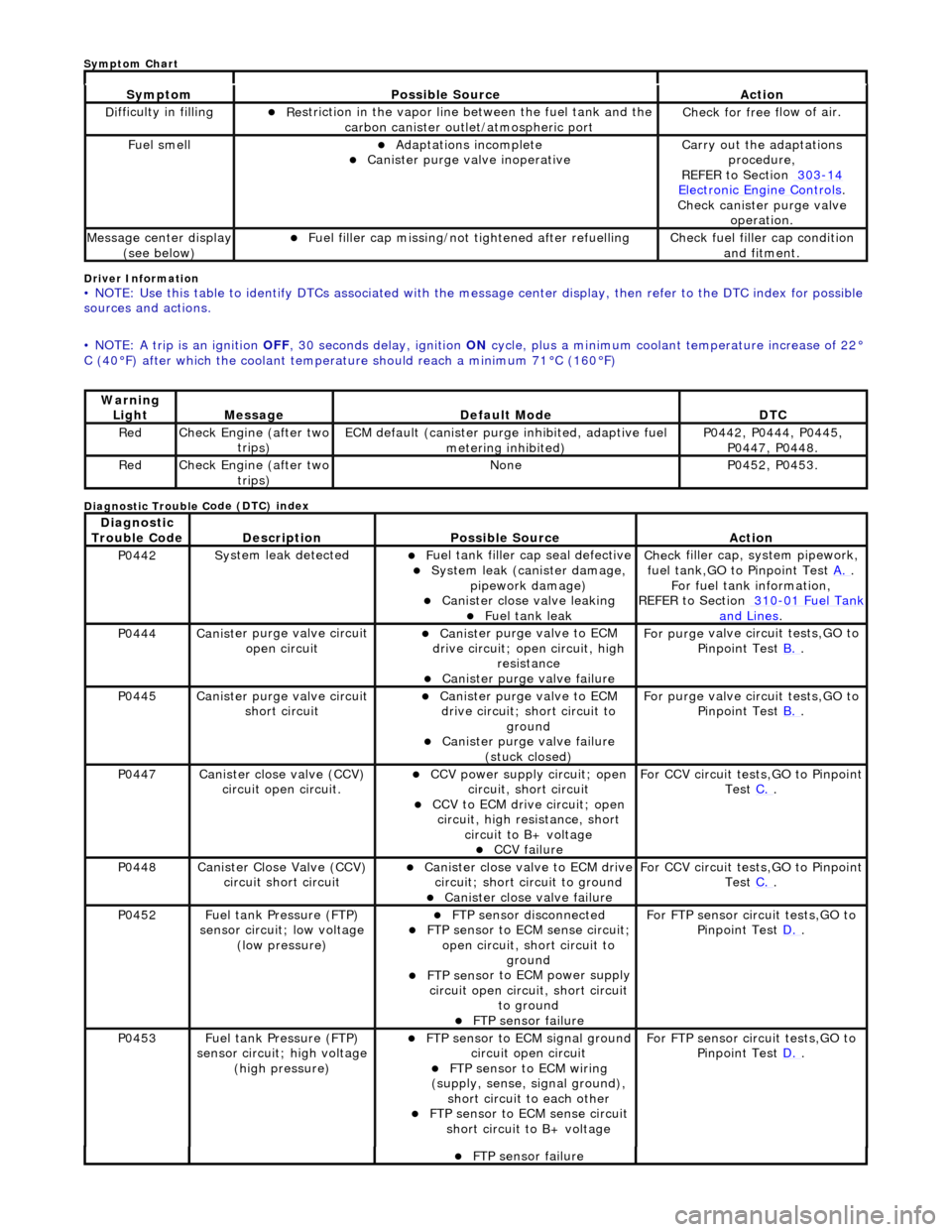
Driver Info
rmation
•
NOTE: Use this table to identify DTCs associated with the me
ssage center display, then refer to the DTC index for possible
sources and actions.
• NOTE: A trip is an ignition OFF, 30 seconds delay, ignition ON cycle, plus a minimum coolant temperature increase of 22°
C (40°F) after which the coolant temperat ure should reach a minimum 71°C (160°F)
Diagnostic Trouble C
ode (DTC) index
Sy
m
ptom
Possib
l
e Source
Acti
o
n
D
i
fficulty in filling
R
e
striction in the vapor line between the fuel tank and the
carbon canister outlet/atmospheric port
Check f or free f
low of air.
F
u
el smell
Adaptat
i
ons incomplete
Cani
st
er purge valve inoperative
Carry
o
ut the adaptations
procedure,
REFER to Section 303
-14 Ele c
tronic Engine Controls
.
Chec k cani
ster purge valve
operation.
M e
ssage center display
(see below)
Fue l
filler cap missing/not
tightened after refuelling
Check fu
el filler cap condition
and fitment.
Warning Li
ght
Mess
age Defaul
t Mode
DT
C
RedCheck Engine (after two
trip
s)
ECM de
fa
ult (canister purge inhibited, adaptive fuel
metering inhibited)
P0442,
P0444, P0445,
P0447, P0448.
Re dCheck Engine (after two
trip
s)
No
neP04 52,
P0453.
Di
agno
stic
Trouble Code
De scr
iption
Possib
l
e Source
Acti
o
n
P0442Sy
st
em leak detected
F
u
el tank filler cap seal defective
Sy
ste
m leak (c
anister damage,
pipework damage)
Cani st
er close valve leaking
F
u
el tank leak
Chec
k fi
ller cap,
system pipework,
fuel tank,GO to Pinpoint Test A.
.
F o
r fuel tank information,
REFER to Section 310
-01 Fu
el Tank
and Lines.
P0444Canist
er purge valve circuit
open circuit
Cani st
er purge valve to ECM
drive circuit; open circuit, high
resistance
Cani st
er purge valve failure
F
or purge
valve circuit tests,GO to
Pinpoint Test B.
.
P0445Canist
er purge valve circuit
short circuit
Cani st
er purge valve to ECM
drive circuit; short circuit to ground
Canist
er purge valve failure
(stuck closed)
F or purge
valve circuit tests,GO to
Pinpoint Test B.
.
P0447Canist
er close valve (CCV)
circuit open circuit.
CCV power su pply ci
rcuit; open
circuit, short circuit
CCV to ECM drive circuit;
open
circuit, high resistance, short circuit to B+ voltage
CCV failure
Fo
r CCV circuit tests,GO to Pinpoint
Test C.
.
P0448Canist
er Close Valve (CCV)
circuit short circuit
Cani st
er close valve to ECM drive
circuit; short circuit to ground
Cani st
er close valve failure
F
o
r CCV circuit tests,GO to Pinpoint
Test C.
.
P0452 Fu
el tank Pressure (FTP)
sensor circuit; low voltage (low pressure)
FTP sen
sor disconnected
FTP sen
sor to ECM sense circuit;
open circuit, short circuit to ground
FTP sens
or to ECM power supply
circuit open circuit, short circuit to ground
FT
P sensor failure
For FT
P se
nsor circuit tests,GO to
Pinpoint Test D.
.
P0453Fu
el tank Pressure (FTP)
sensor circuit; high voltage
(high pressure)
FTP sen
sor to ECM signal ground
circuit open circuit
F T
P sensor to ECM wiring
(supply, sense, signal ground),
short circuit to each other
FTP sen
sor to ECM sense circuit
short circuit to B+ voltage
For FT P se
nsor circuit tests,GO to
Pinpoint Test D.
.
FT
P sensor failure
Sym
ptom Chart
Page 1269 of 2490
2.2. Check on non-volatile diagnostic memory by wr iting a test pattern and then reading it back.
3. 3. Internal 'watchdog' hardware to check whether the TCM has crashed.
Transmission Control Module Supply Voltage
The TCM monitors battery and igni tion switched supply voltages.
A permanent supply is used to maintain a battery backed 'memor y'. Should this supply be cut, due to battery disconnection
perhaps, the 'adaptive shift' valu es will be lost. This will result in a small reduction in shift quality for a period until th e
adaptions are 're-learned'
The TCM will adopt 'limp home' mode as a result of the supply voltage being >16V or <7V with an engine speed >1600
rpm.
Should the ignition supply be >7V but <9V the TCM will hold the gear that it has currently selected. If after 2.5 seconds,
with the engine speed >1600 rpm, the voltage remains at this level, 'limp home' mode will be adopted. The 2.5 second
delay is built in to prevent reaction to a momentary voltage fluctuation.
Operation
CAUTION: Disconnection of the TCM and / or the vehicle batt ery will cause system adaptions to be lost; this may be
apparent by shift quality degradation. Fo llowing reconnection, a period of 'varied' driving will reinstate adaptions and thus
normal operation. Please ensure that the customer is made aware that the adaption period is variable and may occur after
handover, as the transmission re-learns the prevailing driving style.
• NOTE: Should the TCM fail, please ensure that the control housing cooling fan is operating correctly. Failure of the cooling
fan MUST be rectified before renewing the TCM and details of a fan fa ilure should accompany the returned TCM.
The TCM processes information received in both analogue and digital form, such as:
Transmission input speed Transmission output speed Throttle position Pedal demand Gear selector position Engine torque Engine speed Transmission oil temperature Mode switch
This information is then used by the TC M to control shift energy management and decide which shift program to implement
and which gear to select.
The TCM uses the various sensors and inpu ts to monitor the correct operation of the system an d is programmed to take
default action and inform the operator when a fault occurs.
Safety Functions
The safety functions are designed to safeguard against inappr opriate actions by the operator as well as against system
malfunctions. The system prevents reve rse gear from being engaged at high forward speeds and prevents manual
downshifting at excessive engine speeds; these functions are not operational in mechanical limp-home mode.
The TCM constantly monitors the transmissi on for faults. In the event of a problem the TCM will adopt a 'limp home' mode
in which only P R N D - (selector in D but only fourth gear is enabled) are available. The operator will be made aware of
certain faults by an in strument panel warning.
The electrical and diagnostic system has been designed such that system integrity is protected at all times, the safety
concept being based on th e following three points: