Page 2107 of 2490
Installation
7. Position trim finisher for a ccess and withdraw and discard
release button harness grommet from trunk lid.
8. Remove trim finisher from trunk lid.
9. Carefully remove seal from trim finisher.
10. Slacken and remove screws securing release button assembly
to trim finisher and remove release button from finisher.
1. Fit and fully seat release button in trim finisher and fit and
tighten securing screws.
2. Apply suitable adhesive to contac t area of trim finisher and fit
and align seal to finisher.
3. Position trim finisher and pass release button harness through
trunk lid aperture.
Page 2108 of 2490
4.
Fit and fully seat a new harn ess grommet in trunk lid.
5. NOTE: Fit new pressed steel fasteners on Jaguar models.
Align and fully seat trim finisher on trunk lid and fit and fully
tighten securing nuts/fasteners.
6. Connect release button harness multiplug and position harness
in retaining clip.
7. Position and fully seat trunk li d trim pad and secure with new
fir tree fasteners.
8. Fit finisher over trunk latch, fi t and tighten securing bolts and
fit bolt covers..
9. Fit trunk lamp assemblies. Refer to 86.45.16.
10. Connect ground cable to batt ery terminal and fit battery
cover. Refer to 86.15.15.
Page 2113 of 2490
Rear View Mirrors - Auto-Dimming Interior Mirror
Removal and Installation
Removal
Installation
1.
Remove roof console for access and disconnect interior mirror
harness multiplugs. Refer to 76.13.69.90.
2. Remove upper cover from mirror stem.
3. Remove rain sensor unit. Refer to Section 501.16.
4. CAUTION: When removing mirror from base, care must
be exercised to ensure that base is not detached from windshield.
Applying firm downward pre ssure, remove mirror assembly
from base.
1. Position mirror at bottom of base and apply firm upward
pressure to fully seat and secure in position.
2. Install upper cover to mirror stem.
3. Position roof console at head er and connect mirror harness
multiplugs.
4. Install rain sensor unit. Refer to Section 501.16.
5. Install roof console. Refer to 76.13.69.
Page 2114 of 2490
Rear View Mirrors - Exterior Mirror
Removal and Installation
Removal
Installation
1.
Fully open door glass and ease top of door casing away from
door Refer to 76.34.01.
2. Remove door frame cheater trim and memory foam for access.
3. Remove mirror assembly from door.
1. Disconnect mirror harness multiplug.
2. Supporting mirror, slacken and remove securing screw and remove mirror assembly from door.
1. Fit exterior mirror assembly to door.
1. Pass harness and multiplu g through cheater aperture
and position mirror foot on cheater, locating the two
dowels correctly and ensuring correct seating on seal.
Fit and tighten the mirror assembly securing screw.
Connect mirror assembly harness multiplug, position in
door and reposition door foam.
2. Fit memory foam and door frame cheater trim.
3. Close door glass.
4. Fit top of door casing. Refer to 76.34.01.
Page 2115 of 2490
Rear View Mirrors - Exterior Mirror Cover
Removal and Installation
Removal
Installation
1.
Remove exterior mirror glass. Refer to 76.10.53.
2. Remove exterior mirror cap.
1. From housing interior, pr ess out the three cap dowels
complete with securing clips.
Remove mirror cap from casing.
Remove and discard the securing clips.
1. Fit cap to mirror housing.
1. Fit and fully seat new cap securing clips in mirror base.
2. Align mirror cap dowels with the securing clips and press firmly into place.
2. Fit mirror glass. Refer to 76.10.53.
Page 2118 of 2490
Rear View Mirrors - Interior Mirror
Removal and Installation
Removal
CAUTION: When removing mirror from base, care must be exercised to ensure that base is not detached from
windshield.
Installation
1. Remove upper cover from mirror stem.
2. Remove rain sensor unit. Refer to Section 501.16.
3. Applying firm downward pre ssure, remove mirror assembly
from base.
1. Position mirror at bottom of base and apply firm upward
pressure to fully seat and secure in position.
2. Install rain sensor unit. Refer to Section 501.16.
3. Install upper cover to mirror stem.
Page 2121 of 2490

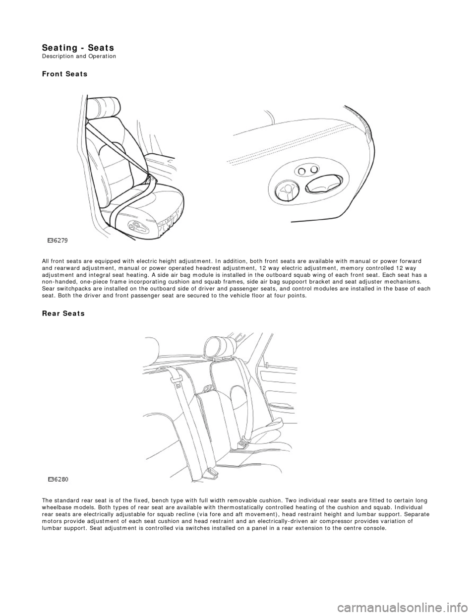
Seating - Seats Description and Operation
Front Seats
All front seats are equipped with electric height adjustment. In addition, both front seats are available with manual or power forward
and rearward adjustment, manual or powe r operated headrest adjustment, 12 way elec tric adjustment, memory controlled 12 way
adjustment and integral seat heating. A side air bag module is installed in the outboard squab wing of each front seat. Each se at has a
non-handed, one-piece frame incorporating cushion and squab frames , side air bag suppoort bracket and seat adjuster mechanisms.
Sear switchpacks are installed on the outboa rd side of driver and passenger seats, and control modules are installed in the bas e of each
seat. Both the driver and front passenger seat ar e secured to the vehicle floor at four points.
Rear Seats
The standard rear seat is of the fixed, bench type with full wi dth removable cushion. Two individual rear seats are fitted to certain long
wheelbase models. Both types of rear seat are available with thermostatically controlled heating of the cushion and squab. Indi vidual
rear seats are electrically adjustable for squab recline (via fore and aft moveme nt), head restraint height and lumbar support. Separate
motors provide adjustment of each seat cushion and head restraint and an electrica lly-driven air compressor provides variation of
lumbar support. Seat adjustment is controll ed via switches installed on a panel in a rear extension to the centre console.
Page 2122 of 2490

Seating - Front Seat
Removal and Installation
Removal
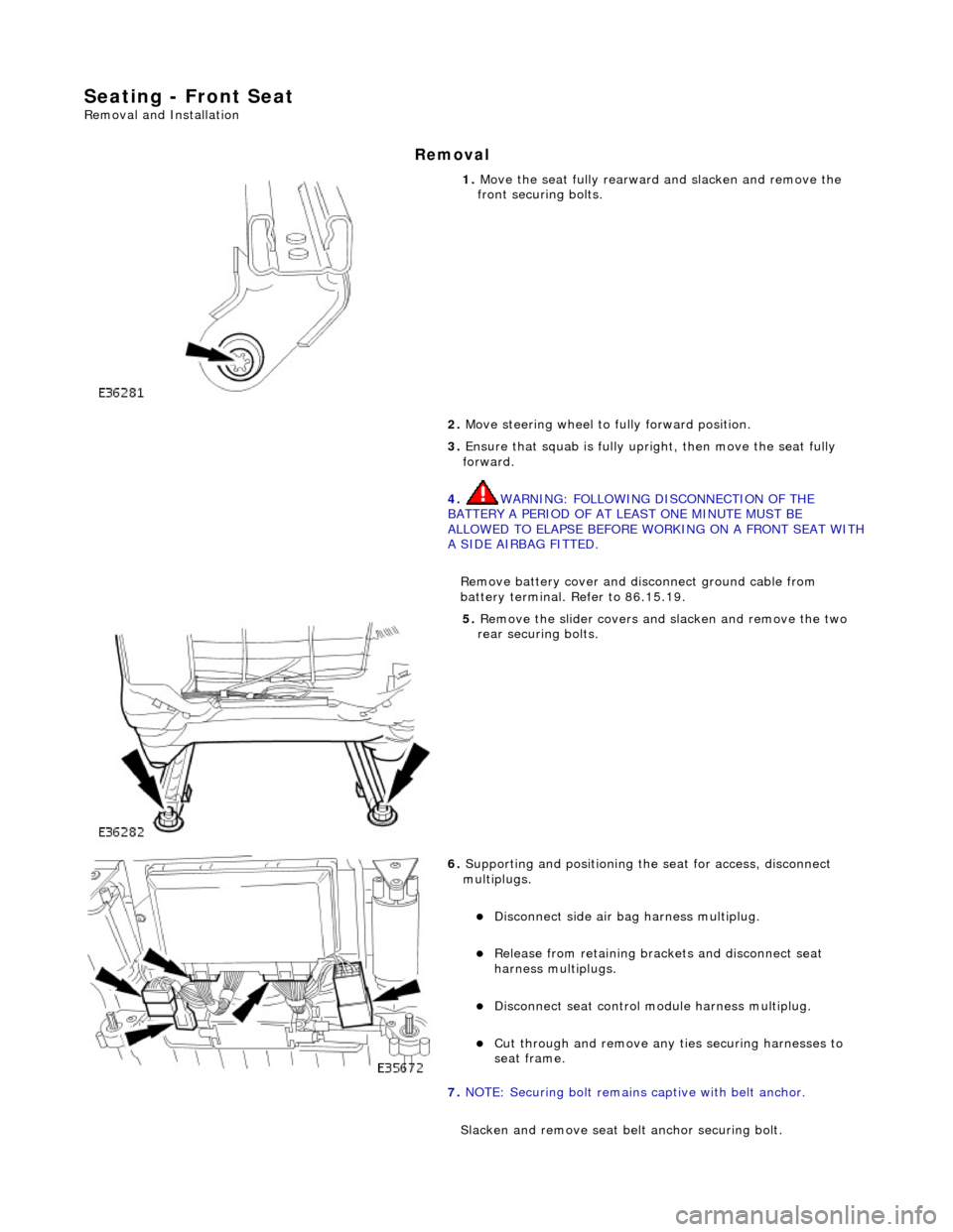
1. Move the seat fully rearward and slacken and remove the
front securing bolts.
2. Move steering wheel to fully forward position.
3. Ensure that squab is fully upright, then move the seat fully
forward.
4. WARNING: FOLLOWING DISCONNECTION OF THE
BATTERY A PERIOD OF AT LEAST ONE MINUTE MUST BE
ALLOWED TO ELAPSE BEFORE WORKING ON A FRONT SEAT WITH
A SIDE AIRBAG FITTED.
Remove battery cover and disc onnect ground cable from
battery terminal. Refer to 86.15.19.
5. Remove the slider covers an d slacken and remove the two
rear securing bolts.
6. Supporting and positioning the seat for access, disconnect
multiplugs.
Disconnect side air bag harness multiplug.
Release from retaining brackets and disconnect seat
harness multiplugs.
Disconnect seat control module harness multiplug.
Cut through and remove any ti es securing harnesses to
seat frame.
7. NOTE: Securing bolt remains captive with belt anchor.
Slacken and remove seat be lt anchor securing bolt.