Page 2090 of 2490
Interior Trim and Ornamentation - Rear Door Trim Panel Finish Panel
Removal and Installation
Removal
Installation
1. Remove interior door handle escutcheon.
Remove cover from door ha ndle escutcheon securing
screw and slacken and remove screw.
Pull door handle inwards and exercising care to avoid
damaging tweeter, remove escutcheon from casing.
2. Remove veneer panel from casing.
1. Using a thin plastic leve r, carefully ease rear of
veneer panel inwards to release the two rear
securing tangs.
2. Slide veneer panel re arwards to release front
retainers.
1. Position veneer panel on casing and slide forward to engage
front retainers.
2. Using a soft pad or cloth, press re ar of panel firmly to seat the
securing tangs.
3. Position door handle escutche on on casing, fit and tighten
securing screw and fit cover over screw.
Page 2093 of 2490
Installation
12. Remove pocket from door casing.
1. Release puddle lamp harness from clips at base of door pocket.
2. Slacken and remove th e two screws securing
bottom of pocket to casing.
3. Remove two spring clips securing top of pocket to casing.
13. Lift pocket from casing
14. Slacken and remove door sp eaker securing screws and
remove speaker from casing.
15. Remove speakere grill from casing
16. Remove casing to to door securing clips.
1. Fit and fully seat casing securing clips.
2. Position speaker grill in casing align speaker and fit and tighten
securing screws.
3. Position pocket in casing and secure with screws and spring
clips.
4. Fit puddle lamp to casing, fit and tighten securing screws and
position harness in pocket clips.
5. Fit door armrest to casing. Refer to 76.34.23.
6. Fit inner waist seal holder to casing and fit and tighten the six
securing screws.
7. CAUTION: Before installing door casing, ensure that
Page 2094 of 2490
primary water shedder is undamag
ed and correctly attached to
door inner panel.
Align and fit inner waist seal.
8. Check that armrest tang locater and screw insert are correctly
positioned in door panel.
9. Position casing for access and connect speaker, puddle lamp
and switchpack harnesses.
10. Finally position casing locating fold over waist flange and
firmly press armrest to locate retaining tang in door panel.
11. Commencing at front , press and firmly seat casing lower
fasteners in door inserts
12. Fit and tighten armrest centre se curing screw in door insert.
13. Fit door veneer panel. Refer to 76.47.12.
14. Position door handle escutche on on casing, fit and tighten
securing screw and fit cover over screw.
Page 2095 of 2490
Interior Trim and Ornamentation - Rear Window Blind
Removal and Installation
Removal
Installation
1.
Remove rear seat cushion. Refer to 76.73.18.
2. Remove rear seat squa b. Refer to 76.70.38.
3. Remove rear parcel tray. Refer to 76.67.06.90
4. Place parcel tray face down on clean bench.
5. Remove sunblind assembly.
Slacken and remove nuts securing sunblind to parcel tray.
Remove washers.
Remove sunblind from parcel tray.
Repeat procedure to remove opposite side sunblind.
1. Position sunblind on parcel tray.
2. Install washers on sunblind studs.
3. Install nuts on sunblind stud s and tighten nuts to 5-7Nm.
4. Repeat above procedure to inst all opposite side sunblind.
5. Install parcel tray/sunblind as sembly. Refer to 76.67.06.90.
6. Install rear seat squa b. Refer to 76.70.38.
7. Install rear seat cushio n. Refer to 76.73.18.
Page 2097 of 2490
Interior Trim and Ornamentation - Scuff Plate Trim Panel
Removal and Installation
Removal
Installation
1. NOTE: The finisher can be easily damaged, care must therefore be exercised during removal.
Using a thin plastic lever and starting at one end, carefully
remove the treadplate finisher and place face uppermost on
sheet of clean dry polythene.
2. Remove treadplate securing sc rews and remove treadplate.
1. Ensure that draught welt is correctly positioned and fully
seated on aperture flange.
2. Position sill tread plate and install three securing screws.
3. Ensure that sill contact area is clean and dry.
4. Install treadplate finisher, pressing firmly into place. If finisher
has been renewe d, remove protective film.
Page 2098 of 2490
Interior Trim and Ornamentation - Sun Visor
Removal and Installation
Removal
Installation
1.
Remove battery cover and disc onnect ground cable from
battery terminal. Refer to 86.15.19.
2. Release sun visor from suppo rt and turn downwards.
3. Supporting the sun visor, sl acken and remove the three
screws securing the mounting to the header.
4. Disconnect the harness multiplug situated behind the
headlining and remove the sun visor.
5. Slacken and remove screw securing sunvisor support, and
remove support from header.
1. Position sun visor at header.
2. Connect multiplug and position it behind headlining.
3. Correctly position and firmly seat sun visor mounting on
header and fit and tighten securing screws.
4. Position sun visor support at header and fit and tighten
securing screw.
5. Connect ground cable to battery terminal and fit battery cover.
Refer to 86.15.15.
Page 2100 of 2490

Exterior Trim and Ornamentation - A-Pillar Moulding LH
Removal and Installation
Removal
Installation
1.
Remove front and rear grab handles. Refer to 76.58.30
2. Remove draught welt from adjace nt section of door aperture
flange.
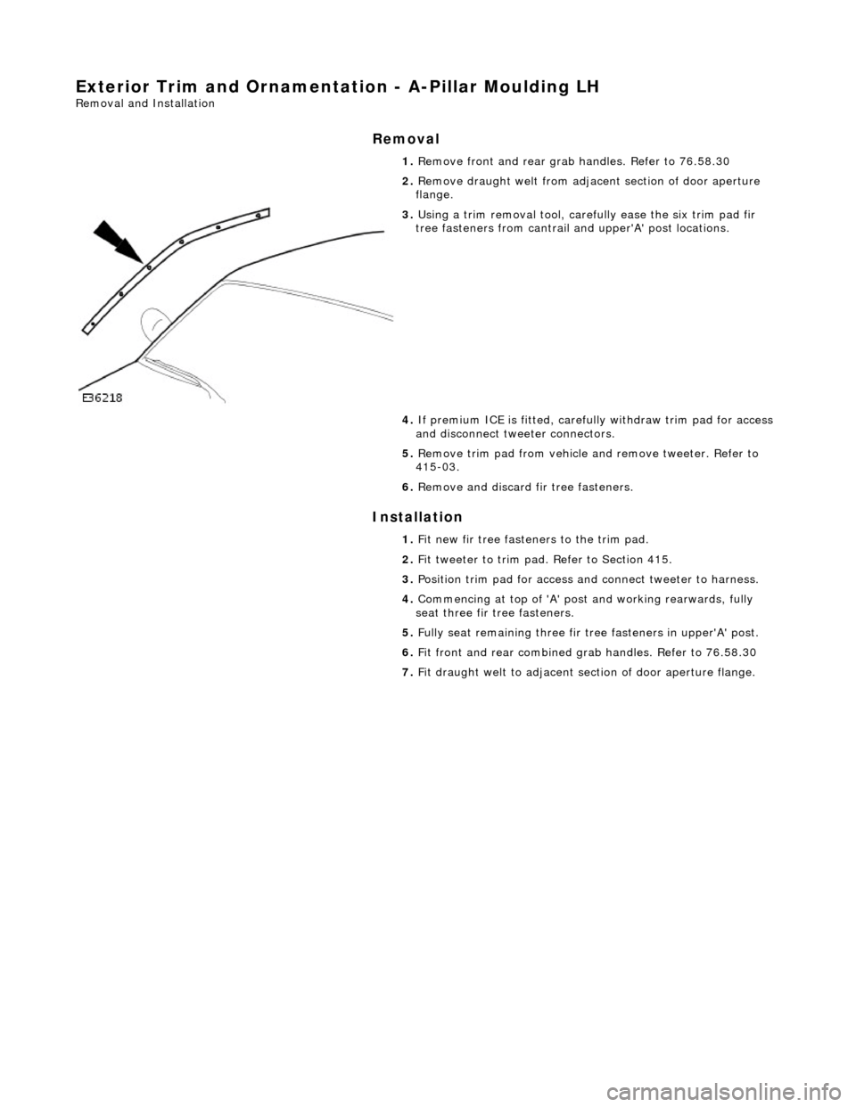
3. Using a trim removal tool, carefu lly ease the six trim pad fir
tree fasteners from cantrail an d upper'A' post locations.
4. If premium ICE is fitt ed, carefully withdraw trim pad for access
and disconnect tweeter connectors.
5. Remove trim pad from vehicle an d remove tweeter. Refer to
415-03.
6. Remove and discard fir tree fasteners.
1. Fit new fir tree fasten ers to the trim pad.
2. Fit tweeter to trim pad. Refer to Section 415.
3. Position trim pad for access and connect tweeter to harness.
4. Commencing at top of 'A' post and working rearwards, fully
seat three fir tree fasteners.
5. Fully seat remaining three fir tr ee fasteners in upper'A' post.
6. Fit front and rear combined gr ab handles. Refer to 76.58.30
7. Fit draught welt to adjacent section of door aperture flange.
Page 2101 of 2490

Exterior Trim and Ornamentation - A-Pillar Moulding RH
Removal and Installation
Removal
Installation
1.
Remove rear grab handle. Refer to 76.58.30.
2. Remove draught welt from adjace nt section of door aperture
flange.
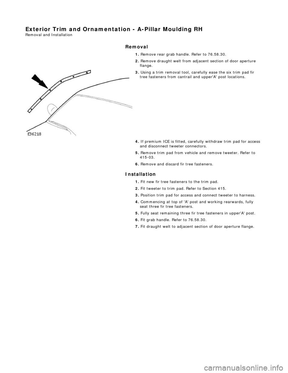
3. Using a trim removal tool, carefu lly ease the six trim pad fir
tree fasteners from cantrail an d upper'A' post locations.
4. If premium ICE is fitt ed, carefully withdraw trim pad for access
and disconnect tweeter connectors.
5. Remove trim pad from vehicle an d remove tweeter. Refer to
415-03.
6. Remove and discard fir tree fasteners.
1. Fit new fir tree fasten ers to the trim pad.
2. Fit tweeter to trim pad. Refer to Section 415.
3. Position trim pad for access and connect tweeter to harness.
4. Commencing at top of 'A' post and working rearwards, fully
seat three fir tree fasteners.
5. Fully seat remaining three fir tr ee fasteners in upper'A' post.
6. Fit grab handle. Refer to 76.58.30.
7. Fit draught welt to adjacent section of door aperture flange.