Page 1256 of 2490
El
ectronic Engine Controls -
Mass Air Flow (MAF) Sensor
Remo
val and Installation
Remov
a
l
1.
Disc onne
ct battery ground cable (IMPORTANT, see SRO
86.15.19 for further information).
2. Disc
onnect connector from MAF sensor.
3. Re
move bolts securing MAF sensor to air cleaner.
4. Re
move air cleaner cover.
Re
lea
se clips.
5. Re
lease band clip - trunking to MAF sensor and remove
assembly.
Di sc
ard sensor seals
Page 1258 of 2490
El
ectronic Engine Controls - Variable
Camshaft Timing (VCT) Oil Control
Solenoid
Re mo
val and Installation
Remova
l
1.
Op
en the engine compartment and fit paintwork protection
sheets.
2. Disc
onnect the batt
ery ground cable.
Re
move the battery cover.
3. Disc
onnect the VVT solenoid connector.
4. Re
move the two bolts which secure the VVT solenoid to the
timing cover.
5. Pull the VVT solenoid clear and discard the O-ring.
Page 1261 of 2490
Automatic Transmission/Transaxle - 4.0L NA V8 - AJ27/3.2L NA V8 - AJ26
- Transmission Descriptio
n
Description an
d Operation
Transmission As
sembly
Int
roduction
Compon
ent Descriptions
The t
orque converter:
Acts as a fluid
coupling between the
engine and transmission geartrain.
P
rovides multiplication of engine torque.
Cons
ists of an impeller, turbine and stat
or, housed within a converter cover.
Has a l
ock-up clutch with variable slip control.
The transmission casing:
Houses the geartrain and elec t
ro-hydraulic control unit.
Contains
the input speed sensor which measures turbine speed.
Contai
ns the output speed sensor which measures the transmission output speed.
It
em
Par
t Number
De
scription
1—Torque c
onverter housing
2—Tran
smission casing
3—Fluid pan
4—Transmission bre
ather
5—Re
ar extension housing
6—16
-way connector
7—Gear s
elector shaft
Page 1262 of 2490

Contains th
e hydraulic system pump.
Contains
th
e fluid temperature sensor.
The epicyclic geartrain:
Provi des fi
ve forward gears and Reverse.
Has
h
ydraulically actuated, multi-disk clutches, to select the required gear ratios.
Feature
s clutch-to-clutch operation to permit
gear shifts for uninterrupted power flow.
The electro-hydraulic control unit:
Is lo c
ated in the lower part of
the unit, within the fluid pan.
Is controlled
by the TCM (transmissio
n control module), and the manual selector valve which is cable operated.
Re
gulates the flow of fluid to the ge
artrain clutches via three solenoid-operated valv es and the manual selector
valve.
Has fi ve pressure
regulators for controll
ing fluid pressures within the system.
Is con
nected to the TCM via a 16-way connector mounted on
the left-hand side of the transmission casing. Refer to
Connector Pins Identification, Section 307-01A.
The hydraulic system pump:
Is l o
cated at the front of the transmission casing.
Is dri
v
en from the impeller hub,
pressurising the fluid whenever the engine is running.
Supplie
s fluid under pressure to the torq
ue converter, geartrain, electro-hydr aulic control unit and the lubrication
circuit.
D r
aws fluid from the fluid pa
n below the transmission casing, through a filter.
The rear extension housing:
Is bolt
ed to the rear of the transmission casing.
Provides the rear engine / transmi
ssion mo
unting point; refer to section 303-01.
Carrie
s the transmission output shaft oil seal.
Filled-for-l
i
fe Fluid System
The
transm
ission is 'filled for life' and
does not require fluid changes, except where extreme driving conditions prevail.
Routine level checking is not required and a dipstick is not pr ovided. A level / filler plug is fitted for level checking and
replenishment, following service actions; see 303-01 General Procedures.
Transmission Torque Converter
Page 1266 of 2490
Operation
The transmission fluid temperature sensor is integrated into the internal harness within the fluid pan.
It should be noted that this component is not serviceable, ne cessitating the renewal of the internal harness should a fault
occur.
Following engine start-up, if the fluid temperature is < 20 °C and does not increase by 10 °C after 180 seconds, a failure
judgement is made. A similar judgement is made should the temperature change by more than 5 °C in <100 milliseconds.
The MIL is illuminated if the failure judgement is made on two successive trips.
Sensor output is continuously monitored for out of range values. If a sustained high, or low inpu t is sensed, indicating a
harness or connector fault, a failure judgement is made.
Location of Sensor Within The Harness
Temperature / Resistance Relationship Chart
Page 1272 of 2490

3.3. Gradient: Under specific speeds and loads
4. 4. Cruise: During cruise control
5. 5. Manual: Shift map when the LH side of the 'J gate' is used
Three specific condition shift maps have a higher priority than the two base shift maps and will intervene when appropriate
conditions prevail for traction, gradient or cruise.
When traction control (engine or brake system derived) is operational the TCM will implement the traction map to maximise
control of wheel slip.
The gradient maps are intended to enhance vehicle drivability when towing or climbing a gradient. The TCM will implement
the maps when increased driving resistan ce is detected and enhanced drivability, cooling and increa sed performance is
appropriate.
The cruise map is intended to minimize unwanted gearshifts and 'hunting' and is activated when cruising near to the set
speed, or resuming.
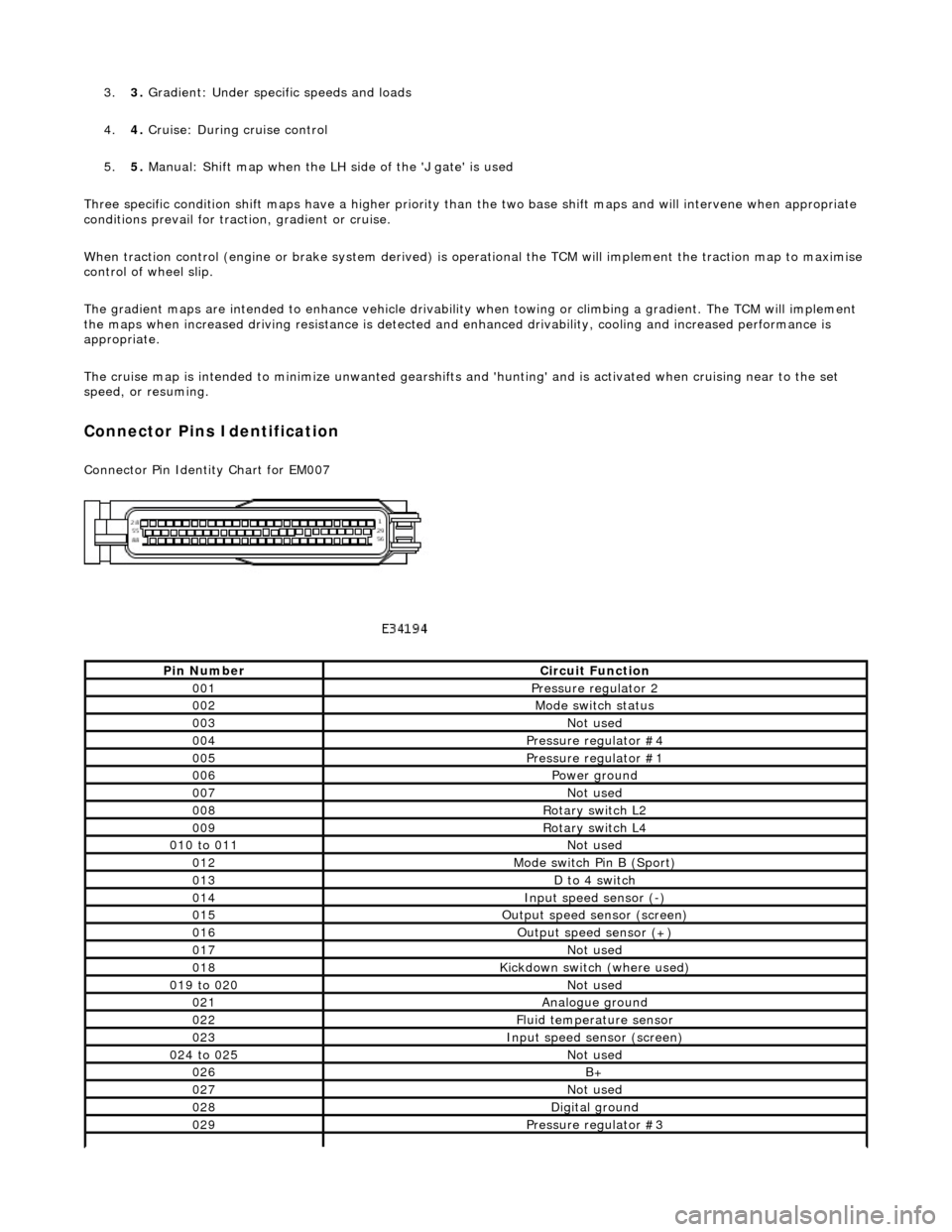
Connector Pins Identification
Connector Pin Identity Chart for EM007
Pin NumberCircuit Function
001Pressure regulator 2
002Mode switch status
003Not used
004Pressure regulator #4
005Pressure regulator #1
006Power ground
007Not used
008Rotary switch L2
009Rotary switch L4
010 to 011Not used
012Mode switch Pin B (Sport)
013D to 4 switch
014Input speed sensor (-)
015Output speed sensor (screen)
016Output speed sensor (+)
017Not used
018Kickdown switch (where used)
019 to 020Not used
021Analogue ground
022Fluid temperature sensor
023Input speed sensor (screen)
024 to 025Not used
026B+
027Not used
028Digital ground
029Pressure regulator #3
Page 1273 of 2490
Connector Pin Identity Chart for CC014
Connector Pin Identity Chart for EM047
030Shift solenoid valve #1
031Not used
032Shift solenoid valve #3
033Shift solenoid valve #2
034Power ground
035Not used
036Rotary switch L1
037Rotary switch L3
038 to 041Not used
042Input speed sensor (+)
043Not used
044Output speed sensor (-)
045Mode switch Pin A (Normal)
046 to 050Not used
051Pressure regulator #5
053Solenoid valve (+)
052Pressure regulator (+)
054Fused ignition (+)
055Fused ignition (+)
056 to 081Not used
082CAN link In (-)
083CAN link In (+)
084Not used
085CAN link Out (-)
086CAN link Out (+)
087JDS L-line (not used)
088JDS K-line (not used)
Pin NumberCircuit Function
112V ignition
2Security LED (power)
3CAN link In (-)
4CAN link In (+)
5Gate illumination (power)
6Security LED (ground)
7Not used
8CAN link Out (-)
9CAN link Out (+)
10Gate illumination (ground)
11Not used
12Not used
Page 1274 of 2490
Connector Pin Identity Chart for EM046
Pin NumberCircuit Function
00APosition L1
00BPosition L2
00CPosition L3
00DPosition L4
00EDigital ground
00FNot used
00GNot used
00HNot used
00JB+
00KPark and neutral switch
Pin NumberCircuit Function
001Output speed sensor (+)
002Pressure regulator #1
003Pressure regulator #2
004Shift solenoid valve #3
005Input speed sensor (+)
006Input speed sensor (-)
007Pressure regulator #3
008Shift solenoid valve #1
009Shift solenoid valve #2
010Output speed sensor (-)
011Pressure regulator #4
012Shift solenoid valves (+)
013Analogue ground
014Fluid temperature sensor
015Pressure regulator #5
016Pressure regulators (+)