Page 1519 of 2490
Align the drive peg and lower sliding block of the switch to
the mating components of the selector mechanism.
2. Install the four screws, bu t do not fully tighten.
Remove the Ty-Strap from the dual linear switch.
Use the manual release and repo sition the selector to 'N'
for installation of the selector cable.
3. Connect the electrical connector to the linear switch.
4. Assemble the cable to the gear shift assembly.
1. Locate the outer cable and fit the inner cable to the gear selector arm. Tighten to 22-28 Nm.
2. Position the abutment nuts to the approximate position, but do not tighten.
5. NOTE: When setting the selector cable, ensure that the
selector lever on the transmission ca sing is still in the 'N' position.
Adjust the selector cable from inside the vehicle.
1. Confirm that the selector lever is in the 'N' position.
2. Adjust the nuts to lock against the bracket without
Page 1520 of 2490
moving the set position of either the gear selector lever or the selector lever on the transmission casing.
3. Tighten to 22-28 Nm.
4. Verify the 'N' setting.
6. Check that all released connec tors are safely insulated and
connect the vehicle battery.
7. Switch ON the ignition.
8. Adjust the position of the linear switch so that the selector 'N'
position graphic illuminates. Ti ghten the four screws to 0,7-1
Nm.
9. Move the gear selector to 'R' to confirm that the 'R' position
graphic illuminates.
10. Check that the engine will start when the gear selector is in
the 'N' and 'P' positions, bu t not in any other position.
11. Move the gear selector to 'N'.
12. Switch OFF the ignition.
13. Disconnect the battery.
14. Install the console assembly, operation 76.25.01.
15. Install the console finisher veneer panel, operation 76.47.26.
16. Install the J-gate surround, operation 76.25.24.
17. Perform the Battery Reconnection Procedure described in
Operation 86.15.15.
Page 1521 of 2490
Automatic Transmission/Transaxle External Contro ls - 4.0L SC V8 - AJ26 -
Selector Lever Knob
Removal and Installation
Removal
Installation
1.
Disconnect the vehicle battery ground lead.
2. Remove the select or lever knob.
1. Slacken the ferrule, rotate clockwise.
2. Rotate the knob coun ter-clockwise to remove.
1. Refer to the illustration.
1. Fit the knob.
2. Refer to the illustration.
Page 1643 of 2490
6. R
aise the vehicle on a ramp.
7. R
emove the bolts which secure
the rear of the front muffler
assembly to the transmission rear mounting.
8. R
emove the bolts which secure
the front flange of the front
muffler to the downpipe flange.
R
epeat for the flange bolt
s on the opposite side.
9. R
emove the gasket from the front
muffler flange at each side.
R
eposition the front silencer rearwards.
R
emove the gasket from each flange.
10
.
Remove the downpipe catalytic converter.
R
emove the bolts which se
cure the downpipe lower
mounting bracket.
Remove the
downpipe assembly.
11. Remove the oxygen sensor(s).
The downstream sensor i
s fitt
ed only for North American
markets.
Page 1650 of 2490
Exha
ust System - Catalytic Conv
erter RH4.0L SC V8 - AJ26
Remo
val and Installation
Remov
a
l
1.
Op
en the engine compartment and fit paintwork protection
sheets.
2. CAUT
ION: Note the position of the upstream and
downstream (where fitted) o xygen sensor multiplugs for
reassembly.
Disconnect the oxygen sensor multiplugs.
Di spl
ace the multiplugs from the engine mounting bracket.
Dis
connect the plug(s) from the oxygen sensor(s).
3.
Re
move the four nuts which se
cure the downpipe catalytic
converter to the exhaust manifold.
4. Raise the vehicle on a ramp.
5. Re
move the bolts which secure
the rear of the front muffler
assembly to the transmission rear mounting.
6. Remove the bolts which secure the front flange of the front
muffler to the downpipe flange.
R e
peat for the flange bolt
s on the opposite side.
Page 1689 of 2490

Fuel System - General Information - Fuel System Pre
ssure Check
Gen
eral Procedures
WARNING: Working on the fuel system re sults in fuel and fuel vapor being present in the atmosphere. Fuel vapor is
extremely flammable, hence great care must be taken whilst working on the fuel system. Adhere strictly to the following
precautions:
D
o not smoke in the work area
Di
splay
NO SMOKING signs around the work area
D
isconnect the battery before
working on the fuel system
Av
oid sparks
Make sure sui
table fire ex
tinguishers are at hand
Make sure absor
bent material is at
hand to soak up any spillage
Make sure the work area is
well ventilated
M
ake sure that the gauge is correctly conn
ected, and that all connections are secure BEFORE starting the engine
DO N
OT
disconnect the gauge from the schrader valve while the engine is running
Make su
re the schrader valve reseals once the gauge is disconnected
• NOTE: Depending on the design of the ga uge set, there may be a drain valve and tube. Make sure this valve is closed, and
the drain tube placed in a suitable container BEFORE connecting the gauge to the schrader valve.
1. Make sure the vehi
cle is in
Park for vehicles with automatic
transmission, Neutral for vehicles with manual transmission.
2. Apply the parking brake.
3. Place suitable absorbent material around the schrader valve to
absorb any spillage when connecting the gauge set.
4. Remove the protective cap from the schrader valve.
5. Connect the gauge, using adaptors if required.
6. Remove the absorbent material and dispose of safely.
7. Disconnect and plug the vacuum hose from the pressure
regulator.
8. Start the engine and record the fuel pressure reading.
As a gui
de, the fuel pressu
re should be approximately 3.0
bar (44.1 psi) with the regulator disconnected.
9. With the engine still running, reconnect the vacuum hose to
the pressure regulator an d record the reading.
Th
e pressure should dr
op to approximately 2.6 bar (38
psi) when the vacuum hose is reconnected.
10. Switch off the engine.
11. Place more absorbent material around the schrader valve.
12. Where fitted, open the drain valve and allow the fuel from the
gauge and line to flow into the container to depressurize the
system.
13. Disconnect and remove the gauge set and any adaptors.
14. Clean up any fuel which may have been spilt and remove the
absorbent material. Dispose of safely.
15. Refit and secure the protective cap to the schrader valve.
16. Reconnect the fuel pressure regulator vacuum hose.
17. Start the engine and make sure there are no leaks.
Page 1743 of 2490

Accelerati
on Control - Accelerator Cable Adjustment
Gen
eral Procedures
1.
Load the Approved Jaguar Diagno stic System with power train
data logger.
2. Connect the Approved Jaguar Diag nostic System to the vehicle.
3. W
ith 'Disable Network Integrity Test - YES/ NO' displayed on
the screen select YES.
4. With new menu displayed on the screen, select ' Engine
Management'.
5. Turn the ignition to ON.
R
emove any previously selected data logger parameters.
6. On data logger select PPS11 an d PPS2 (Pedal demand sensors
1 and 2).
7. On Sedan models only, remove the bulkhead covers on both
sides and the engine compartment rear cover.
8. Cut, remove and discard the ra tchet strap which retains the
throttle cable to the abutment bracket.
9. Ensure there is no tension on the throttle cable by releasing
the throttle cable adjustment nut from the abutment bracket.
10. Record the voltages for both sensors, PPS11 and PPS2.
11. Partially insert the throttle cable adjustment nut into the
abutment bracket.
12. Recheck the voltages for both sensors, PPS11 and PPS2.
13. Where the voltages at step 12 are higher than the voltages
taken at step 10, contin ue to step 15 below.
14. Where the voltages at step 12 are the same as the voltages
taken at step 10, contin ue to step 16 below.
15. Rotate the adjustment nut clockwise (as viewed from the
front of the vehicle) until the same voltages are indicated as in
step 10. Continue to turn thro ugh a part revolution until the
sides of the nut are vertical. Tu rn through a further 90 degrees,
then fully insert the nut into the abutment bracket.
16. Rotate the adjustment nut anti-clockwise (as viewed from the
front of the vehicle) until the indicated voltage starts to
increase. Then rotate the nut clockwise through a part
revolution until the sides are ve rtical. Turn through a further 90
degrees, then fully insert the nut into the abutment bracket.
17. Fit a new ratchet strap to secure the throttle cable adjusting
nut to the abutment bracket.
18. Operate the throttle pedal through 20 full cycles to settle the
cable. Check the voltages now shown, remain the same as in
steps 15 and 16.
19. Check and where necessary adjust the kickdown switch. For
additional information, refer to Section 307
-05A Automatic Transmissi
on/Transaxle External Controls
Sectio
n
307
-05
B
Au
tomatic Transmission/Tra
nsaxle External Controls
.
20
.
On Sedan models only, refit the engine compartment rear
cover and the bulkhead co vers on both sides.
21. Switch the ignition OFF and disconnect the Approved Jaguar
Diagnostic System.
Page 1808 of 2490

Air Conditioning - Condenser Core
Removal and Installation
Removal
1. Disconnect battery ground cable (IMPORTANT, see SRO
86.15.19 for further information).
2. Drain radiator coolant only; refer to 26.10.01 or (SC)
26.10.01.
3. Recover refrigerant from air co nditioning system; refer to
82.30.30.
4. Release both gas struts, set the engine cover fully forward to
the service access position an d support with a wooden (or
similar) strut.
5. CAUTION: Take care not to damage hood or radiator
grille.
Remove twin fan and motor as sembly; refer to 26.25.12.
6. Disconnect radiator bleed hose.
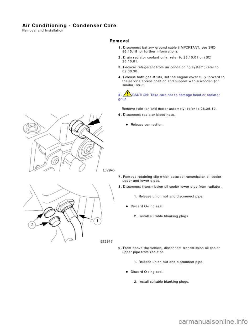
Release connection.
7. Remove retaining clip which secures transmission oil cooler
upper and lower pipes.
8. Disconnect transmission oil cooler lower pipe from radiator.
1. Release union nut and disconne ct pipe.
Discard O-ring seal.
2. Install suitable blanking plugs.
9. From above the vehicle, discon nect transmission oil cooler
upper pipe from radiator.
1. Release union nut and disconne ct pipe.
Discard O-ring seal.
2. Install suitable blanking plugs.