1998 JAGUAR X308 303
[x] Cancel search: 303Page 1025 of 2490
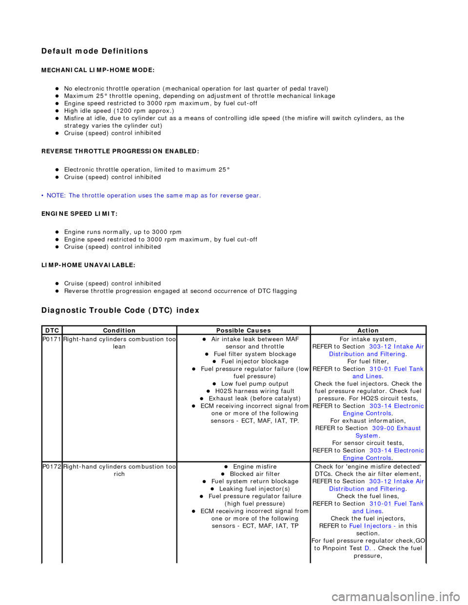
Default mode Definitions
MECH
ANICAL LIMP-HOME MODE:
No el
ectronic throttle operation (mechanical
operation for last quarter of pedal travel)
M
aximum 25° throttle opening,
depending on adjustment of th rottle mechanical linkage
Engine
speed restricted to 3000
rpm maximum, by fuel cut-off
Hi
gh idle speed (1200 rpm approx.)
Misfire
at idle, due to cylinder cut as a means of control
ling idle speed (the misfire will switch cylinders, as the
strategy varies th e cylinder cut)
Cruise (speed) contr
ol inhibited
REVERSE THROTTLE PROGRESSION ENABLED:
El
ectronic throttle operation, limited to maximum 25°
Cruise (speed) contr
ol inhibited
• NOTE: The throttle oper ation uses the same map as for reverse gear.
ENGINE SPEED LIMIT:
Engine
runs normally, up to 3000 rpm
Engine
speed restricted to 3000
rpm maximum, by fuel cut-off
Cruise (speed) contr
ol inhibited
LIMP-HOME UNAVAILABLE:
Cruise (speed) contr
ol inhibited
R
everse throttle pr
ogression engaged at second occurrence of DTC flagging
Diagnostic Trouble Code (D
TC) index
DT
C
Cond
ition
P
ossible Causes
Acti
on
P0171Right-hand cylinders combustion too
leanAir
intake leak between MAF
sensor and throttle
F
uel filter system blockage
F
uel injector blockage
F
uel pressure regulator failure (low
fuel pressure)
Low f
uel pump output
H0
2S harness wiring fault
E
xhaust leak (before catalyst)
ECM receivi
ng incorrect signal from
one or more of the following
sensors - ECT, MAF, IAT, TP.
Fo
r intake system,
REFER to Section 303
-12
Intake Air
Distribu
tion and Filtering
.
F
or fuel filter,
REFER to Section 310
-01
Fuel Tank
and Lines.
Chec
k the fuel injectors. Check the
fuel pressure regu lator. Check fuel
pressure. For HO2S circuit tests,
REFER to Section 303
-14
Electronic
Engine
Controls
.
F
or exhaust information,
REFER to Section 309
-00
Exhaust
Sy
stem
.
For se
nsor circuit tests,
REFER to Section 303
-14
Electronic
Engine
Controls
.
P0172Right-hand cylinders combustion too
ri
ch
Engine
misfire
Bl
ocked air filter
F
uel system return blockage
Leak
ing fuel injector(s)
F
uel pressure regulator failure
(high fuel pressure)
ECM receivi
ng incorrect signal from
one or more of the following sensors - ECT, MAF, IAT, TP
Chec
k for 'engine misfire detected'
DTCs. Check the air filter element,
REFER to Section 303
-12
Intake Air
Distribu
tion and Filtering
.
Chec
k the fuel lines,
REFER to Section 310
-01
Fuel Tank
and Lines.
Chec
k the fuel injectors,
REFER to Fuel Injectors
- in t
his
section.
For fuel pressure regulator check,GO
to Pinpoint Test D.
.
Check the fuel
pressure,
Page 1026 of 2490
REFE
R to Section 310
-00
Fu
el
Sy
ste
m
- General
Information
.
Check f o
r DTCs indicating a sensor
fault,
REFER to Section 303
-14 El
ectronic
Engine
C
ontrols
.
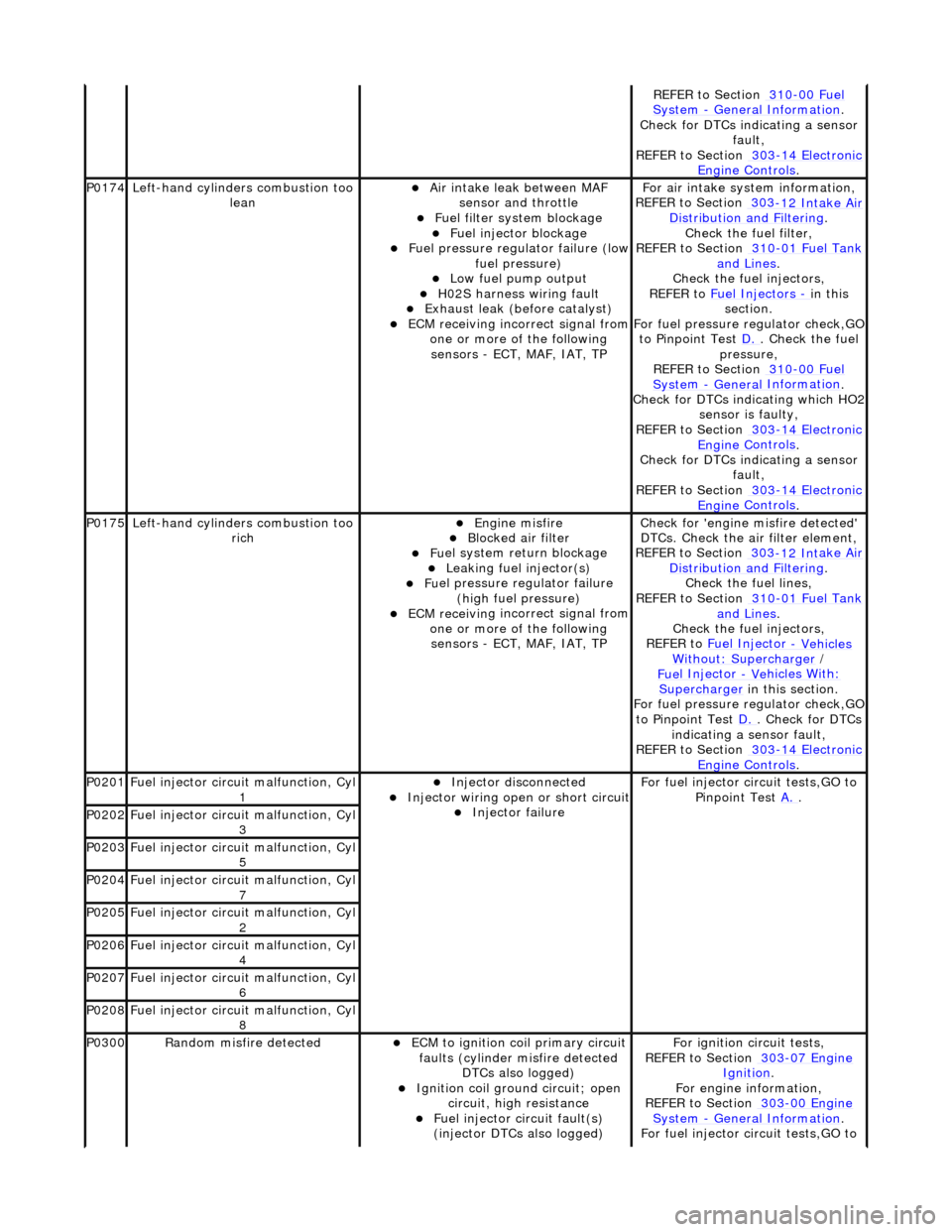
P0174
Left-hand cyl i
nders combustion too
lean
Air in
take leak between MAF
sensor and throttle
F u
el filter system blockage
F
u
el injector blockage
F
u
el pressure regulator failure (low
fuel pressure)
Low f u
el pump output
H0
2S harness wiri
ng fault
E
x
haust leak (before catalyst)
ECM receivi
n
g incorrect signal from
one or more of the following sensors - ECT, MAF, IAT, TP
F o
r air intake sy
stem information,
REFER to Section 303
-12 Int
ake Air
Distribu tion and Filterin
g
.
Check the fuel fi lter,
REF
ER to Section 310
-01
Fu
el Tank
and Lines.
Chec k the
fuel injectors,
REFER to Fuel Injectors
- in t h
is
section.
For fuel pressure regulator check,GO
to Pinpoint Test D.
. Ch
eck the fuel
pressure,
REFER to Section 310
-00 Fu
el
Sy
ste
m
- General
Information
.
Check f o
r DTCs indicating which HO2
sensor is faulty,
REFER to Section 303
-14 El
ectronic
Engine
C
ontrols
.
Check f o
r DTCs indicating a sensor
fault,
REFER to Section 303
-14 El
ectronic
Engine
C
ontrols
.
P0175Left-hand cyli
nders combustion too
rich
Engine m
isfire
Bl
ocked air
filter
F
u
el system return blockage
Leak
i
ng fuel injector(s)
F
u
el pressure regulator failure
(high fuel pressure)
ECM receivi n
g incorrect signal from
one or more of the following sensors - ECT, MAF, IAT, TP
Check for 'en
gine misfire detected'
DTCs. Check the air filter element,
REFER to Section 303
-12 Int
ake Air
Distribu tion and Filterin
g
.
Chec k the
fuel lines,
REFER to Section 310
-01 Fu
el Tank
and Lines.
Chec k the
fuel injectors,
REFER to Fuel Injector
- Vehicles Wi
thout: Supercharger
/
Fue
l Injector
- Ve
hicles With
:
Supercharger
in this
section.
For fuel pressure regulator check,GO
to Pinpoint Test D.
. Check for DT
Cs
indicating a sensor fault,
REFER to Section 303
-14 El
ectronic
Engine
C
ontrols
.
P0201F
u
el injector circuit malfunction, Cyl
1
Injector discon n
ected
Inject
or wir
ing open or short circuit
Injector fail
ure
F
o
r fuel injector circuit tests,GO to
Pinpoint Test A.
.
P0202Fu
el injector circuit malfunction, Cyl
3
P0203F u
el injector circuit malfunction, Cyl
5
P0204F u
el injector circuit malfunction, Cyl
7
P0205Fu
el injector circuit malfunction, Cyl
2
P0206Fu
el injector circuit malfunction, Cyl
4
P0207F u
el injector circuit malfunction, Cyl
6
P0208F u
el injector circuit malfunction, Cyl
8
P0300Ran d
om misfire detected
ECM t
o
ignition coil primary circuit
faults (cylinder misfire detected DTCs also logged)
Ignition coil ground circuit; open
ci
rcuit, high resistance
F
u
el injector circuit fault(s)
(injector DTCs also logged)
F o
r ignition circuit tests,
REFER to Section 303
-07 En
gine
Ignition.
F or engi
ne information,
REFER to Section 303
-00 En
gine
Sy
ste
m
- General
Information
.
F o
r fuel injector circuit tests,GO to
Page 1027 of 2490
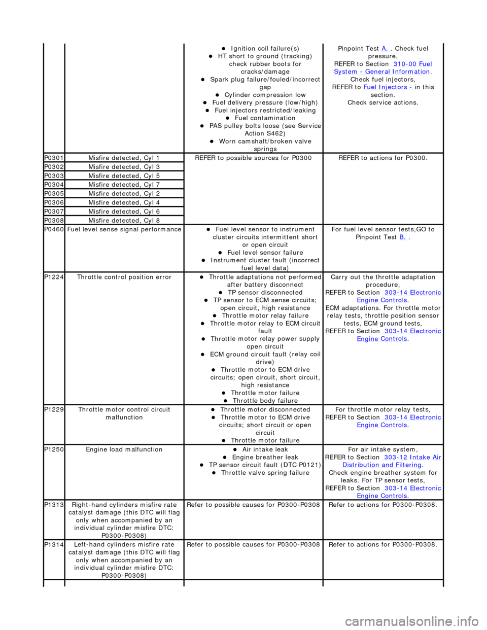
Ignition coil
failure(s)
HT sho
rt to ground (tracking)
check rubber boots for cracks/damage
Spark plug
failure/fouled/incorrect
gap
Cy
linder compression low
F
uel delivery pressure (low/high)
F
uel injectors restricted/leaking
Fuel contamination
P
AS pulley bolts loose (see Service
Action S462)
W
orn camshaft/broken valve
springs
P
inpoint Test
A.
.
Check fuel
pressure,
REFER to Section 310
-00
Fuel
Sy
stem
- General
Information
.
Chec
k fuel injectors,
REFER to Fuel Injectors
- in t
his
section.
Check service actions.
P0301Misfire
detected, Cyl 1
R
EFER to possible sources for P0300
R
EFER to actions for P0300.
P0302Misfire
detected, Cyl 3
P0303Misfire
detected, Cyl 5
P0304Misfire
detected, Cyl 7
P0305Misfire
detected, Cyl 2
P0306Misfire
detected, Cyl 4
P0307Misfire
detected, Cyl 6
P0308Misfire
detected, Cyl 8
P0460F
uel level sense signal performance
Fue
l level sensor
to instrument
cluster circuits in termittent short
or open circuit
F
uel level sensor failure
Instrument cluster
faul
t (incorrect
fuel level data)
F
or fuel level sensor tests,GO to
Pinpoint Test B.
.
P1224Throttl
e control position error
Thro
ttle adaptations not performed
after battery disconnect
TP se
nsor disconnected
TP se
nsor to ECM sense circuits;
open circuit, hi gh resistance
Throttl
e motor relay failure
Th
rottle motor relay to ECM circuit
fault
Throttl
e motor relay power supply
open circuit
ECM ground circuit faul
t (relay coil
drive)
Throttl
e motor to ECM drive
circuits; open circuit, short circuit, high resistance
Throttl
e motor failure
Throttl
e body failure
Carry
out the throttle adaptation
procedure,
REFER to Section 303
-14
Electronic
Engine
Controls
.
ECM adaptations. For
throttle motor
relay tests, throttle position sensor tests, ECM ground tests,
REFER to Section 303
-14
Electronic
Engine
Controls
.
P1229Throttl
e motor control circuit
malfunction
Throttl
e motor disconnected
Throttl
e motor to ECM drive
circuits; short circuit or open circuit
Throttl
e motor failure
Fo
r throttle moto
r relay tests,
REFER to Section 303
-14
Electronic
Engine
Controls
.
P1250Engine
load malfunction
Air
intake leak
Engine
breather leak
TP se
nsor circuit fault (DTC P0121)
Throttl
e valve spring failure
F
or air intake system,
REFER to Section 303
-12
Intake Air
Distribu
tion and Filtering
.
Chec
k engine breather system for
leaks. For TP sensor tests,
REFER to Section 303
-14
Electronic
Engine
Controls
.
P1313Right-hand cylinders misfire rate
cat
alyst damage (this DTC will flag
only when accompanied by an
individual cylinder misfire DTC: P0300-P0308)
R
efer to possible causes for P0300-P0308
R
efer to actions for P0300-P0308.
P1314L
eft-hand cylinders misfire rate
catalyst damage (this DTC will flag only when accompanied by an
individual cylinder misfire DTC: P0300-P0308)
R
efer to possible causes for P0300-P0308
R
efer to actions for P0300-P0308.
Page 1028 of 2490
Pinpoint Tests
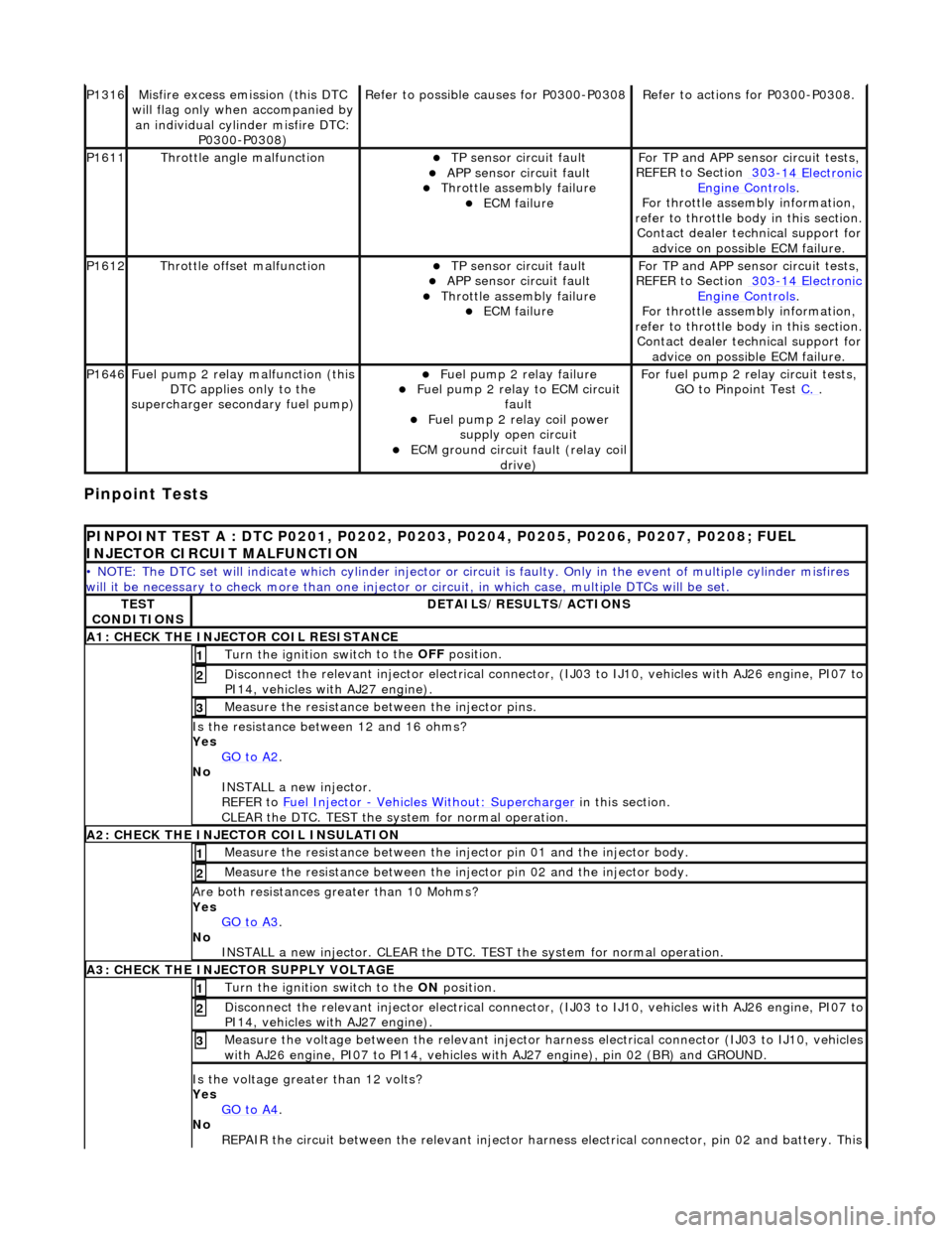
P1316Mi
sfire excess emission (this DTC
will flag only when accompanied by an individual cylinder misfire DTC: P0300-P0308)
Re
fer to possible causes for P0300-P0308
R
e
fer to actions for P0300-P0308.
P1611Thr
o
ttle angle malfunction
TP sensor
ci
rcuit fault
APP sensor circuit faul
t Throttle
assembly failure
ECM failu
r
e
F
or TP and APP
sens
or circuit tests,
REFER to Section 303
-14 El
ectronic
Engine
C
ontrols
.
F o
r throttle assembly information,
refer to throttle body in this section.
Contact dealer technical support for advice on possible ECM failure.
P1612Throttl e
offset malfunction
TP sensor
ci
rcuit fault
APP sensor circuit faul
t Throttle
assembly failure
ECM failu
r
e
F
or TP and APP
sens
or circuit tests,
REFER to Section 303
-14 El
ectronic
Engine
C
ontrols
.
F o
r throttle assembly information,
refer to throttle body in this section.
Contact dealer technical support for advice on possible ECM failure.
P1646Fu
el pump 2 relay malfunction (this
DTC applies only to the
supercharger secondary fuel pump)
Fu
el pump 2 relay failure
Fu
el pump 2 relay to ECM circuit
fault
Fu
el pump 2 relay coil power
supply open circuit
ECM ground circuit faul t (relay coil
drive)
For fuel pump 2 r
elay circuit tests,
GO to Pinpoint Test C.
.
PI
NPOINT TEST A : DTC P0201, P0202, P0203, P0204, P0205, P0206, P0207, P0208; FUEL
INJECTOR CIRCUIT MALFUNCTION
• NOTE
: The DTC set will indicate which cylinder injector or circ
uit is faulty. Only in the event of multiple cylinder misfires
will it be necessary to chec k more than one injector or circuit, in which case, multiple DTCs will be set.
TES
T
CONDITIONS
D E
TAILS/RESULTS/ACTIONS
A1
: CH
ECK THE INJECTOR COIL RESISTANCE
Turn the ignition swi
t
ch to the OFF
position.
1
Disconne
ct the relevant injector electrical connector
, (IJ03 to IJ10, vehicles with AJ26 engine, PI07 to
PI14, vehicles with AJ27 engine).
2
Meas ure t
he resistance between the injector pins.
3
Is
t
he resistance between 12 and 16 ohms?
Yes GO to A2
.
No
INST
ALL a new injector.
REFER to Fuel Injector
- Ve hicles With
out: Supercharger
in this
section.
CLEAR the DTC. TEST the system for normal operation.
A2: CHECK
THE INJECTOR COIL INSULATION
Meas
ure t
he resistance between the inje
ctor pin 01 and the injector body.
1
Measure t
he resistance between the inje
ctor pin 02 and the injector body.
2
Are both re
sistances greater than 10 Mohms?
Yes GO to A3
.
No
INST
ALL a new injector. CLEAR the DTC. TE
ST the system for normal operation.
A3: CHECK THE INJECTOR
SUPPLY VOLTAGE
Turn the ignition swi
t
ch to the ON
position.
1
Disconne
ct the relevant injector electrical connector
, (IJ03 to IJ10, vehicles with AJ26 engine, PI07 to
PI14, vehicles with AJ27 engine).
2
Meas ure t
he voltage between the relevant injector harness electrical connector (IJ03 to IJ10, vehicles
with AJ26 engine, PI07 to PI 14, vehicles with AJ27 engine), pin 02 (BR) and GROUND.
3
Is the volt
age greater than 12 volts?
Yes GO to A4
.
No
R
EPAIR the circuit between the relevant injector harn
ess electrical connector, pin 02 and battery. This
Page 1037 of 2490
Fuel Ch
arging and Controls
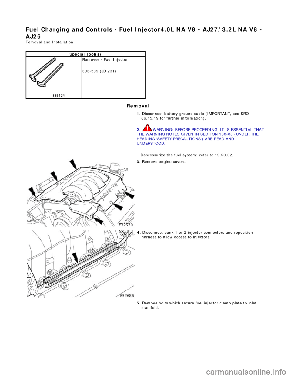
- Fuel Injector4.0L NA V8 - AJ27/3.2L NA V8 -
AJ26
Re
moval and Installation
Remov
al
S
pecial Tool(s)
R
emover - Fuel Injector
303-539 (JD 231)
1. Disconnect battery ground cable (IMPORTANT, see SRO
86.15.19 for further information).
2. WARNING: BEFORE PROCEEDING, IT IS ESSENTIAL THAT
THE WARNING NOTES GIVEN IN SECTION 100-00 (UNDER THE
HEADING 'SAFETY PRECAUTIONS') ARE READ AND
UNDERSTOOD.
Depressurize the fuel sy stem; refer to 19.50.02.
3. R
emove engine covers.
4. Di
sconnect bank 1 or 2 inject
or connectors and reposition
harness to allow access to injectors.
5. Remove bolts which secure fuel injector clamp plate to inlet
manifold.
Page 1066 of 2490
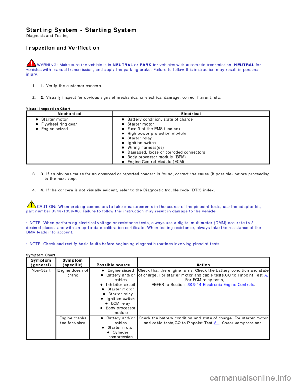
Starting System - Starting System
Diagn
osis and Testing
I
n
spection and Verification
W
A
RNING: Make sure
the vehicle is in NEUTRAL or PARK for vehicles with au tomatic transmission, NEUTRAL for
vehicles with manual transmissi on, and apply the parking brake. Failure to foll ow this instruction may result in personal
injury.
1. 1. Verify the customer concern.
2. 2. Visually inspect for obvious signs of mechanical or electrical damage, correct fitment, etc.
Vi
sual Inspection Chart
3.
3. If an obvi
ous cause for an observed or
reported concern is found, correct th e cause (if possible) before proceeding
to the next step.
4. 4. If the concern is not visually evident, refer to the Diagnostic trouble code (DTC) index.
CAUTION: When probing connectors to take measurements in the course of the pinpoint tests, use the adaptor kit,
part number 3548-1358-00. Failure to follow this in struction may result in damage to the vehicle.
• NOTE: When performing electrical voltag e or resistance tests, always use a digital multimeter (DMM) accurate to 3
decimal places, and with an up-t o-date calibration certificate. When testing resistance, always take the resistance of the
DMM leads into account.
• NOTE: Check and rectify basic faults before beginning diagnostic ro utines involving pinpoint tests.
Sym
ptom Chart
MechanicalElectrical
Starte
r motor
Flywheel
ring gear
Engine
s
eized
Batter
y condition, state of charge
Starte
r motor
F
u
se 3 of the EMS fuse box
High
power protec ti
on module
Starter relay Ignition switc
h
W
i
ring harness(es)
Damaged, loose or corroded connector
s
Body processor module (B
PM)
Engine
C
ontrol Module (ECM)
Sy
m
ptom
(
gene r
al)
Sy
m
ptom
(specific)
Possib l
e source
Acti
o
n
No
n
-Start
Engine does
not
crankEngine s
iezed
Batt
ery and
/or
cables
Inhibitor circuit St arte
r motor
Starter relay Ignition switc
h
ECM relay Body processor
modu le
Check that
the engine turns. Check the battery condition and state
of charge. For starter motor and ca ble tests,GO to Pinpoint Test A.
. For ECM relay
tests,
REFER to Section 303
-14
Electronic Engine Controls
.
Engine
c
ranks
too fast/slow
Batt ery and
/or
cables
St arte
r motor
Cy
linder
com
pression
Check the battery con
dition
and st
ate of charge. For starter motor
and cable tests,GO to Pinpoint Test A.
. Chec
k compressions.
Page 1078 of 2490
• NO
TE: When performing electrical voltag
e or resistance tests, always use a digital multimeter (DMM) accurate to 3
decimal places, and with an up-t o-date calibration certificate. When testing resistance, always take the resistance of the
DMM leads into account.
• NOTE: Check and rectify basic faults before beginning diagnostic ro utines involving pinpoint tests.
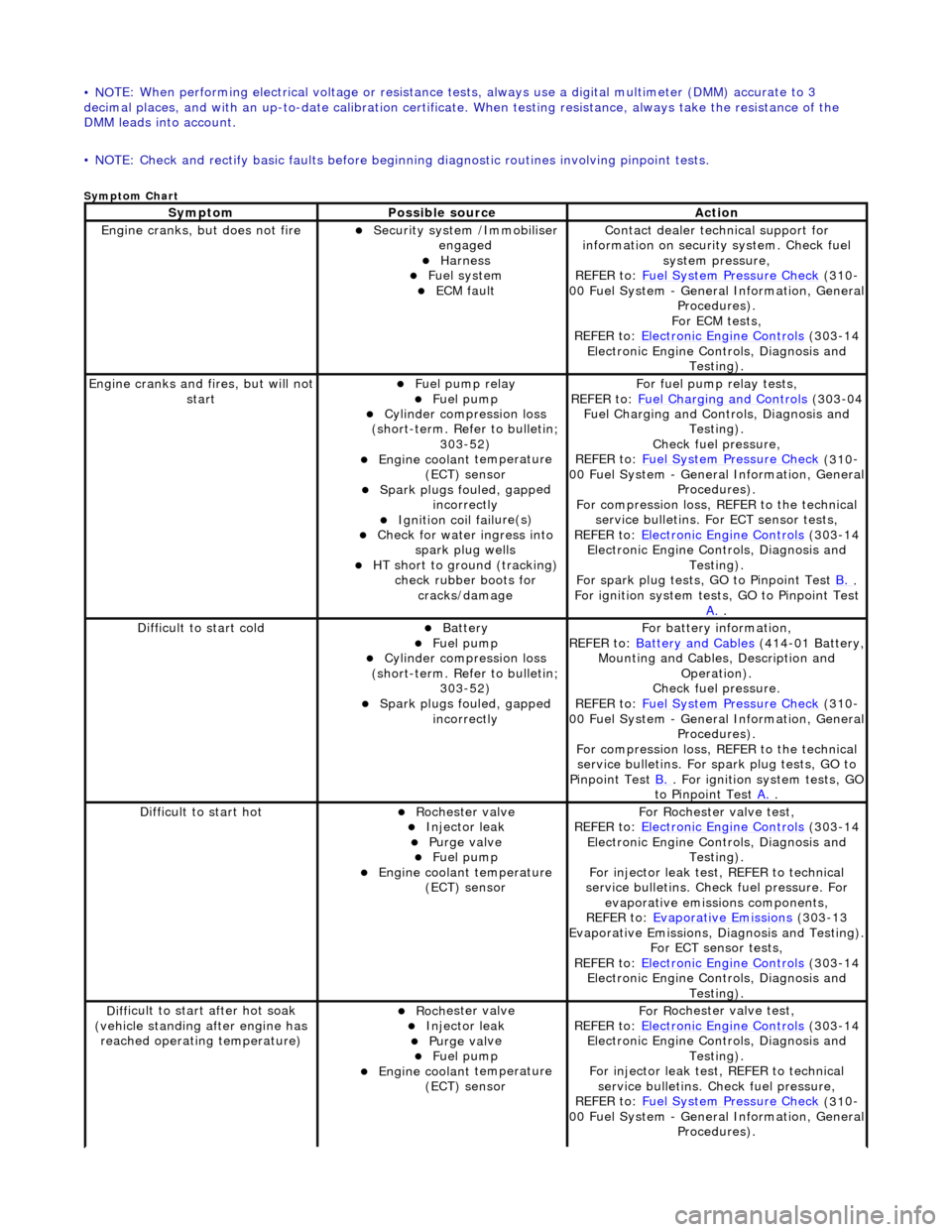
Sym
ptom Chart
Sy
m
ptom
Possib
l
e source
Acti
o
n
Engine
cranks, but does
not fire
Secu
rit
y system /Immobiliser
engaged
Harness Fue l
system
ECM fault
Contact deal er techni
cal support for
information on security system. Check fuel
system pressure,
REFER to: Fuel System Pressure Check
(310
-
00 Fuel System - Genera l Information, General
Procedures).
For ECM tests,
REFER to: Electronic Engine Controls
(303
-14
Electronic Engine Co ntrols, Diagnosis and
Testing).
Engine cranks and
fi
res, but will not
start
Fu
el pump relay
Fuel
pump
Cyl
i
nder compression loss
(short-term. Refer to bulletin; 303-52)
Engine coolan t
temperature
(ECT) sensor
Spark plugs fouled, gapp
ed
incorrectly
Ignition coil fail
ure(s)
Check f
o
r water ingress into
spark plug wells
HT sho rt to ground (tracking)
check rubber
boots for
cracks/damage
Fo
r fuel pump relay tests,
REFER to: Fuel Charging and Controls
(303
-04
Fuel Charging and Controls, Diagnosis and Testing).
Check fuel pressure,
REFER to: Fuel System Pressure Check
(310
-
00 Fuel System - Genera l Information, General
Procedures).
For compression loss, REFER to the technical service bulletins. For ECT sensor tests,
REFER to: Electronic Engine Controls
(303
-14
Electronic Engine Co ntrols, Diagnosis and
Testing).
For spark plug tests, GO to Pinpoint Test B.
.
For ign i
tion system tests, GO to Pinpoint Test
A.
.
Diff
icult to start cold
Batt
ery Fuel
pump
Cyl
i
nder compression loss
(short-term. Refer to bulletin; 303-52)
Spark plugs fouled, gapp
ed
incorrectly
F o
r battery information,
REFER to: Battery and Cables
(414
-01 Battery,
Mounting and Cables, Description and Operation).
Check fuel pressure.
REFER to: Fuel System Pressure Check
(310
-
00 Fuel System - Genera l Information, General
Procedures).
For compression loss, REFER to the technical service bulletins. For spark plug tests, GO to
Pinpoint Test B.
. For ig
nition system tests, GO
to Pinpoint Test A.
.
Diff
icult to start hot
Roc
h
ester valve
Injec
t
or leak
Purge
val
ve
Fue
l
pump
Engine coolan
t
temperature
(ECT) sensor
F or R
ochester
valve test,
REFER to: Electronic Engine Controls
(303
-14
Electronic Engine Co ntrols, Diagnosis and
Testing).
For injector leak test, REFER to technical
service bulletins. Check fuel pressure. For evaporative emissions components,
REFER to: Evaporative Emissions
(303
-13
Evaporative Emissions, Diagnosis and Testing).
For ECT sensor tests,
REFER to: Electronic Engine Controls
(303
-14
Electronic Engine Co ntrols, Diagnosis and
Testing).
D iff
icult to start after hot soak
(vehicle standing after engine has reached operating temperature)
Roc h
ester valve
Injec
t
or leak
Purge
val
ve
Fue
l
pump
Engine coolan
t
temperature
(ECT) sensor
F or R
ochester
valve test,
REFER to: Electronic Engine Controls
(303
-14
Electronic Engine Co ntrols, Diagnosis and
Testing).
For injector leak test, REFER to technical service bulletins. Check fuel pressure,
REFER to: Fuel System Pressure Check
(310
-
00 Fuel System - Genera l Information, General
Procedures).
Page 1080 of 2490
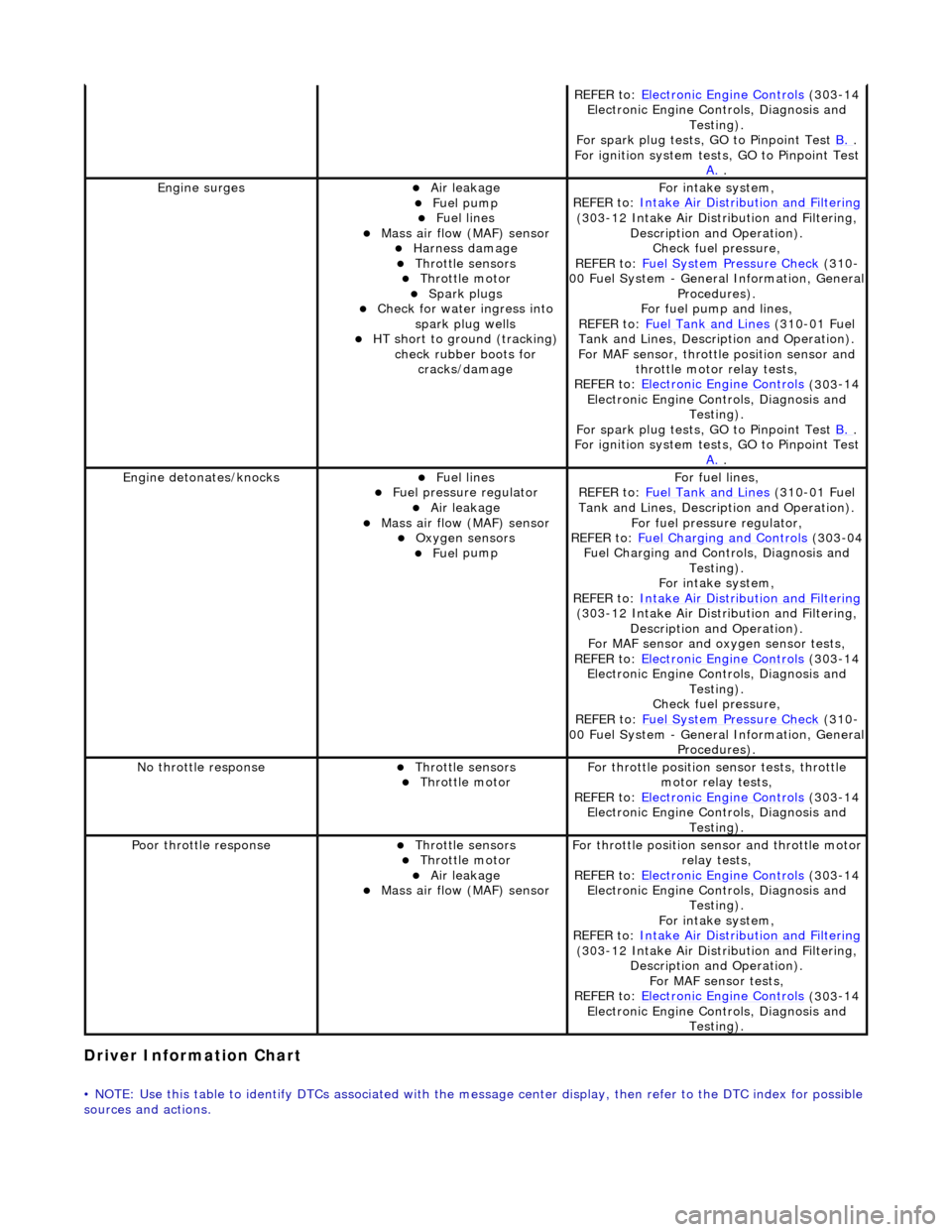
Driver Information
Chart
•
NOTE: Use this table to identify DTCs associated with the me
ssage center display, then refer to the DTC index for possible
sources and actions.
REF E
R to:
Electronic Engine Controls
(303
-14
Electronic Engine Co ntrols, Diagnosis and
Testing).
For spark plug tests, GO to Pinpoint Test B.
.
For ign i
tion system tests, GO to Pinpoint Test
A.
.
Engine s
urges
Air leakage
Fue
l
pump
Fue
l
lines
Mass ai
r fl
ow (MAF) sensor
Harness damage Throttl
e
sensors
Throttl
e
motor
Spark plugs
Check fo
r water ingress into
spark plug wells
HT short to ground (tracking) check rubber
boots for
cracks/damage
Fo r
intake system,
REFER to: Intake Air Distribution and Filtering
(30 3
-12 Intake Air Distribution and Filtering,
Description and Operation). Check fuel pressure,
REFER to: Fuel System Pressure Check
(310
-
00 Fuel System - Genera l Information, General
Procedures).
For fuel pump and lines,
REFER to: Fuel Tank and Lines
(310
-01 Fuel
Tank and Lines, Description and Operation).
For MAF sensor, throttle position sensor and
throttle motor relay tests,
REFER to: Electronic Engine Controls
(303
-14
Electronic Engine Co ntrols, Diagnosis and
Testing).
For spark plug tests, GO to Pinpoint Test B.
.
For ign i
tion system tests, GO to Pinpoint Test
A.
.
Engine detonates/k
nocks
Fue
l
lines
F
u
el pressure regulator
Air leakage
Mass air fl
ow (MAF) sensor
O
xygen senso
rs
Fue
l
pump
F
o
r fuel lines,
REFER to: Fuel Tank and Lines
(310
-01 Fuel
Tank and Lines, Description and Operation).
For fuel pressure regulator,
REFER to: Fuel Charging and Controls
(303
-04
Fuel Charging and Controls, Diagnosis and Testing).
For intake system,
REFER to: Intake Air Distribution and Filtering
(30 3
-12 Intake Air Distribution and Filtering,
Description and Operation).
For MAF sensor and oxyg en sensor tests,
REFER to: Electronic Engine Controls
(303
-14
Electronic Engine Co ntrols, Diagnosis and
Testing).
Check fuel pressure,
REFER to: Fuel System Pressure Check
(310
-
00 Fuel System - Genera l Information, General
Procedures).
No t
hrottle response
Throttl
e
sensors
Throttl
e
motor
Fo
r th
rottle position sensor tests, throttle
motor relay tests,
REFER to: Electronic Engine Controls
(303
-14
Electronic Engine Co ntrols, Diagnosis and
Testing).
Poor throttle responseThrottl e
sensors
Throttl
e
motor
Air leakage Mass air fl
ow (MAF) sensor
F
or throttl
e position se
nsor and throttle motor
relay tests,
REFER to: Electronic Engine Controls
(303
-14
Electronic Engine Co ntrols, Diagnosis and
Testing).
For intake system,
REFER to: Intake Air Distribution and Filtering
(30 3
-12 Intake Air Distribution and Filtering,
Description and Operation). For MAF sensor tests,
REFER to: Electronic Engine Controls
(303
-14
Electronic Engine Co ntrols, Diagnosis and
Testing).