Page 507 of 2490

The driver air bag is moun
ted below the horn operat
ing pad area, adjacent to the steering wheel hub.
For air bag safety and service information, refer to Section 501
-20A Safety Belt
System
Sectio
n
501
-2
0B Supplemental
Re
straint System
.
Upper Steering Column
Motorized Upper Colu
mn Assembly
The motorized upper steering column:
Is adjustable for both til
t and reach.
Has a col
umn adjustment switch installed on
the left-hand side of the lower cowl.
W
ill automatically move to the uppermost tilt and innermost reach position, when the automatic driver entry and exit
function is selected.
Has an instrument li
ghti
ng dimmer switch installed on the left-hand side of the lower cowl.
The steering column adjustment switch:
Controls steeri
ng column reach by
movement of the switch towards an d away from the steering wheel.
Controls steeri
ng column tilt by mo
vement of the switch up and down.
Has two
rotary positions, AUTO and OFF, for selecting the
automatic entry and exit steering column tilt function.
It
em
Par
t Number
De
scription
1-Upper
cowl
2-Lower cowl
3-Ste
ering column adjustment switch
4-Di
mmer switch
Page 508 of 2490
The te
lescopic slider provides driver crash
protection by retracting automatically in the event of an accident; it is clamped in
position to a preset torque.
The motorized upper steering column has the following serviceable parts:
Igniti
on switch assembly.
Igni
ti
on key interlock solenoid.
Ti
lt
motor assembly.
Reach motor assembly.
Manu al Upper Column Assembly
Ite
m
Par
t
Number
De
scr
iption
1-L
o
wer mounting bracket
2-Crash tube
3-Harnes
s c
onnector bracket
4-Tilt motor
5-Reach m
otor
6-Upper
moun
ting bracket
7-Ignition switc
h
(hidden)
8-Igni
ti
on key interlock solenoid
9-S
t
eering wheel mounting shaft
It
e
m
Par
t
Number
De
scr
iption
1-Upper
cowl
2-Lower cowl
3-Colu
mn tilt adjustment lever
4-Col
u
mn reach adjustment lever
5-Di
mm
er switch
Motorized Upper Co
lumn Components
Page 509 of 2490

Is adjustable for both til
t and reach.
Has ca
ble operated reach adjustment, using a rack an
d wedge, with approximately 16 latched positions.
Has si
x latched tilt positions steppe
d at approximately 3° intervals.
Has an u
nlatched top tilt position, allowing the column to be
pulled down to engage the first detent without using the
tilt lever.
Has an instrument li
ghti
ng dimmer switch installed on the left-hand side of the lower cowl.
Manual Upper Column Components
The telescopic slider provides driver crash protection by retracting automatically in the event of an accident; it is clamped in
position to a preset torque.
The manual upper steering column has the following serviceable parts:
Igni
tion switch assembly.
Igni
tion key interlock solenoid.
Bowden
cable and lever assembly.
It
em
Par
t Number
De
scription
1-L
ower mounting bracket
2-Crash tube
3-Harnes
s connector bracket
4-Upper
mounting bracket
5-Ignition switc
h (hidden)
6-Igni
tion key interlock solenoid
7-S
teering wheel mounting shaft
The manu
al upper
steering column:
Page 518 of 2490

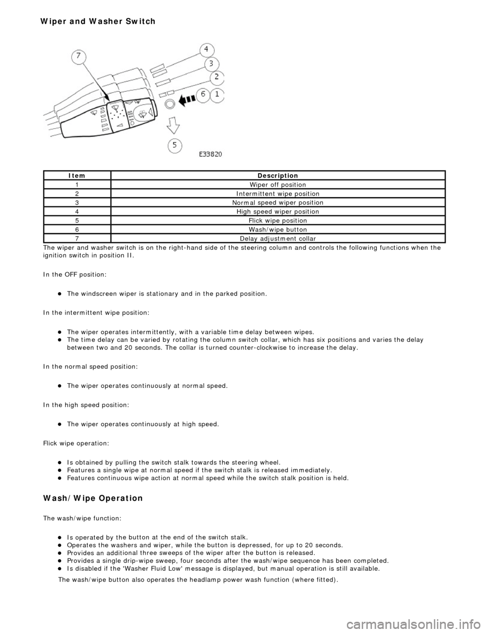
The wiper and washer switch i s
on the righ
t-hand side of the steering column and controls the fo llowing functions when the
ignition switch in position II.
In the OFF position:
The windscreen wiper is stationary and in the parked positio
n.
In the intermittent wipe position:
The wi per ope
rates intermittently, with
a variable time delay between wipes.
The time del
ay can be varied by rotating the column sw
itch collar, which has six positions and varies the delay
between two and 20 seconds. The collar is turned counter-clockwise to increase the delay.
In the normal speed position:
The wiper oper a
tes continuously at normal speed.
In the high speed position:
The wiper ope r
ates continuously at high speed.
Flick wipe operation:
Is obt
ained by pulling the switch
stalk towards the steering wheel.
F
e
atures a single wipe at normal speed if
the switch stalk is released immediately.
Fe
atures continuous wipe action
at normal speed while the swit ch stalk position is held.
Wash/W
ipe Operation
Th
e
wash/wipe function:
Is operat
ed by th
e button at the end of the switch stalk.
Op
erate
s the washers and wiper, while the butt
on is depressed, for up to 20 seconds.
Provides an addit
ional three sweeps of
the wiper after the button is released.
Provid
es a single drip-wipe sweep, four seconds af
ter the wash/wipe sequence has been completed.
Is disabled if the 'Washer Flu
id Low' message is di
splayed, but manual operat ion is still available.
Ite
m
De
scr
iption
1W
i
per off position
2Intermittent
wipe position
3Normal
speed wiper position
4High
speed wiper position
5Flick wipe position
6Wa
sh/wipe button
7D
e
lay adjustment collar
The was
h
/wipe button also operates the head
lamp power wash function (where fitted).
Wiper and Washer Switch