Page 2121 of 2490

Seating - Seats Description and Operation
Front Seats
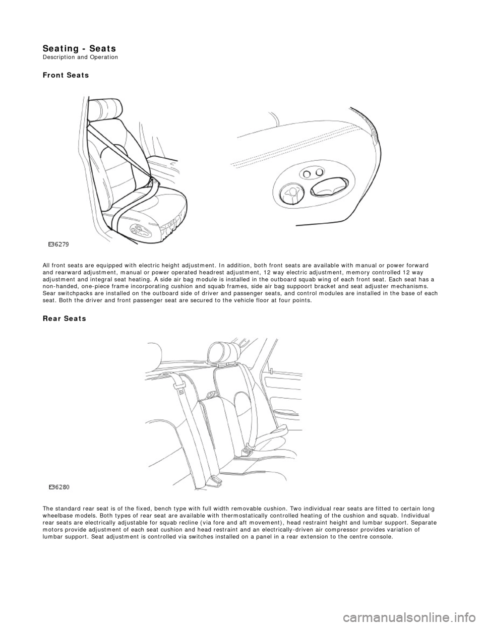
All front seats are equipped with electric height adjustment. In addition, both front seats are available with manual or power forward
and rearward adjustment, manual or powe r operated headrest adjustment, 12 way elec tric adjustment, memory controlled 12 way
adjustment and integral seat heating. A side air bag module is installed in the outboard squab wing of each front seat. Each se at has a
non-handed, one-piece frame incorporating cushion and squab frames , side air bag suppoort bracket and seat adjuster mechanisms.
Sear switchpacks are installed on the outboa rd side of driver and passenger seats, and control modules are installed in the bas e of each
seat. Both the driver and front passenger seat ar e secured to the vehicle floor at four points.
Rear Seats
The standard rear seat is of the fixed, bench type with full wi dth removable cushion. Two individual rear seats are fitted to certain long
wheelbase models. Both types of rear seat are available with thermostatically controlled heating of the cushion and squab. Indi vidual
rear seats are electrically adjustable for squab recline (via fore and aft moveme nt), head restraint height and lumbar support. Separate
motors provide adjustment of each seat cushion and head restraint and an electrica lly-driven air compressor provides variation of
lumbar support. Seat adjustment is controll ed via switches installed on a panel in a rear extension to the centre console.
Page 2271 of 2490

Instrument Panel and Console - Steering Column Lower Shroud
Removal and Installation
Removal
Installation
1.
Move driver seat fully rearward.
2. Remove battery cover and disconnect ground cable from
battery terminal.Refer to 86.15.19.
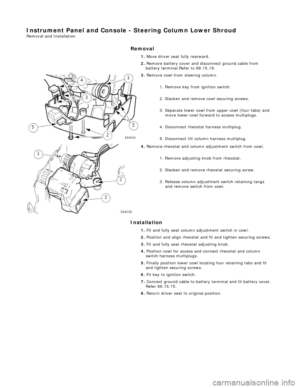
3. Remove cowl from steering column.
1. Remove key from ignition switch.
2. Slacken and remove cowl securing screws.
3. Separate lower cowl from upper cowl (four tabs) and move lower cowl forward to access multiplugs.
4. Disconnect rheostat harness multiplug.
5. Disconnect tilt column harness multiplug.
4. Remove rheostat and column adjustment switch from cowl.
1. Remove adjusting knob from rheostat.
2. Slacken and remove rh eostat securing screw.
3. Release column adjustment switch retaining tangs and remove switch from cowl.
1. Fit and fully seat column ad justment switch in cowl.
2. Position and align rheostat and fit and tighten securing screws.
3. Fit and fully seat rheo stat adjusting knob.
4. Position cowl for access and connect rheostat and column
switch harness multiplugs.
5. Finally position lower cowl locating four retaining tabs and fit
and tighten securing screws.
6. Fit key to ignition switch.
7. Connect ground cable to battery terminal and fit battery cover.
Refer 86.15.15.
8. Return driver seat to original position.
Page 2318 of 2490

Installation
1.
Position motor in housing and fi t and tighten securing nuts and
bolts.
2. Apply suitable lubricant to bore of new spindle inner seal and
fit seal over motor spindle.
3. Holding the capillary and purge valve clear, position
motor/housing assembly on bulkhead.
4. Seat motor spindle seal correctly in upper plenum aperture and
ensure that housing lo cates on lower studs.
5. Fit and tighten the housin g upper securing bolts.
6. Fit and tighten the housing lower securing screws and slide
locking clips inwards.
7. Position throttle cable adjustment bracket on throttle body and
fit and tighten securing bolts.
8. Position purge valve bracket at bulkhead and fit and tighten
securing bolt and nuts.
9. Position engine harness multiplu g on mounting bracket and fit
and tighten securing nut.
10. Connect motor harness multiplug and locate in retaining clip.
11. Apply suitable lubricant to bore of new outer seal and fit with
washer to motor spindle.
12. Fit and fully tighten collar nut on motor spindle.
13. Fit plenum cover. Refer to 76.10.01.
14. Fit wiper arm and blade. Refer to 84.15.44.90.
15. Fit top covers to LH and RH bulkheads and rear of engine
compartment. refer to 76.11.33 and 76.11.35.
16. Fit ground cable to battery te rminal and cover to battery.
Refer to 86.15.15.
Page 2320 of 2490

Installation
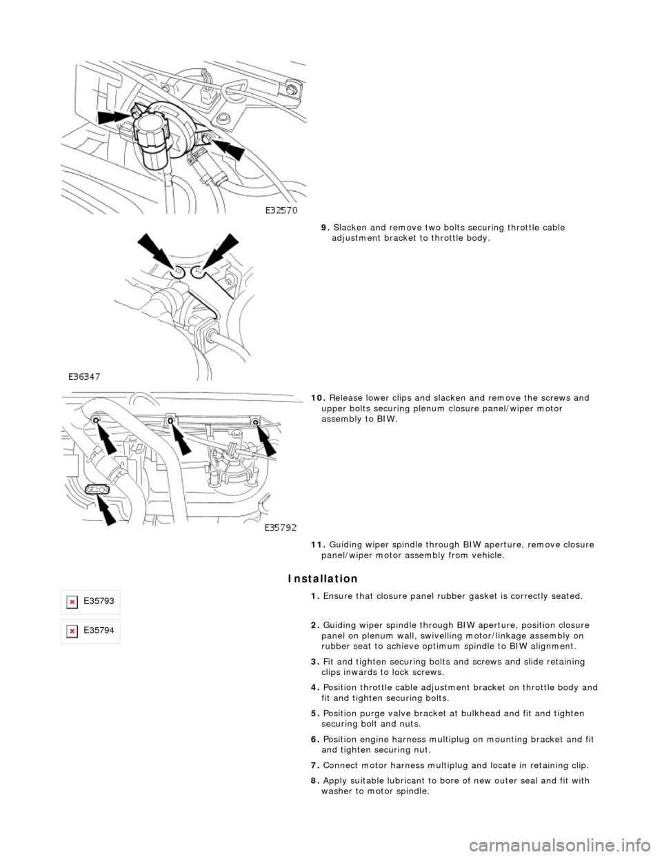
9. Slacken and remove two bolts securing throttle cable
adjustment bracket to throttle body.
10. Release lower clips and slacken and remove the screws and
upper bolts securing plenum closure panel/wiper motor
assembly to BIW.
11. Guiding wiper spindle through BIW aperture, remove closure
panel/wiper motor assembly from vehicle.
E357931. Ensure that closure panel rubbe r gasket is correctly seated.
E357942. Guiding wiper spindle through BI W aperture, position closure
panel on plenum wall, swivelling motor/linkage assembly on
rubber seat to achieve optimu m spindle to BIW alignment.
3. Fit and tighten securing bolts and screws and slide retaining
clips inwards to lock screws.
4. Position throttle cable adjustment bracket on throttle body and
fit and tighten securing bolts.
5. Position purge valve bracket at bulkhead and fit and tighten
securing bolt and nuts.
6. Position engine harness multiplu g on mounting bracket and fit
and tighten securing nut.
7. Connect motor harness multiplug and locate in retaining clip.
8. Apply suitable lubricant to bore of new outer seal and fit with
washer to motor spindle.