Page 2166 of 2490

Seating - Rear Seat Cushion Removal and Installation
Removal
Installation
1.
Heated rear seat only. Remove battery cover and disconnect ground
cable from battery terminal. Refer to 86.15.19.
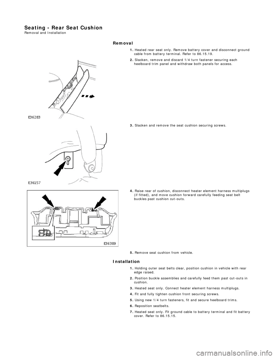
2. Slacken, remove and discard 1/4 turn fastener securing each
heelboard trim panel and withdraw both panels for access.
3. Slacken and remove the seat cushion securing screws.
4. Raise rear of cushion, disconnect heater element harness multiplugs
(if fitted), and move cushion forw ard carefully feeding seat belt
buckles past cushion cut-outs.
5. Remove seat cushion from vehicle.
1. Holding outer seat belts clear, posi tion cushion in vehicle with rear
edge raised.
2. Position buckle assemblies and carefully feed them past cut-outs in
cushion.
3. Heated seat only. Connect heat er element harness multiplugs.
4. Fit and fully tighten cushion front securing screws.
5. Using new 1/4 turn fasteners, fi t and secure heelboard trims.
6. Reposition seatbelts.
7. Heated seat only. Fit ground cable to battery terminal and fit battery
cover. Refer to 86.15.15.
Page 2332 of 2490

Roof Opening Panel - Roof Opening Panel Frame
Removal and Installation
Removal
1. Adjust front passenger seat fu lly rearwards and fully recline
seat squab.
2. Remove battery cover and disc onnect ground cable from
battery terminal. Refer to 86.15.19.
3. Remove sliding roof flange finisher. Refer to 76.82.23.
4. Remove sliding roof trim panel. Refer to 76.82.19.
5. Remove grab handles. Refer to 501-05.
6. Remove roof console. Refer to 76.13.69.90.
7. Remove sun visors. Refer to 501-05.
8. Remove cantrail/upper A post trims. Refer to 76.13.20.
9. Remove rear quarter trim s. Refer to 76.13.13.
10. Remove front half headlining for access. refer to 76.64.15.90.
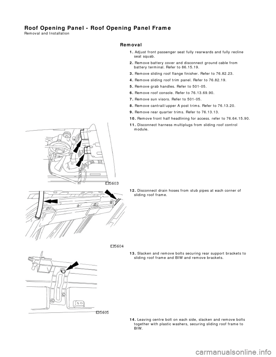
11. Disconnect harness multiplugs from sliding roof control
module.
12. Disconnect drain hoses from stub pipes at each corner of
sliding roof frame.
13. Slacken and remove bolts securi ng rear support brackets to
sliding roof frame and BIW and remove brackets.
14. Leaving centre bolt on each side, slacken and remove bolts
together with plastic washers, securing sliding roof frame to
BIW.
Page 2334 of 2490
tighten securing bolts.
7.
Align rear support brackets and tighten securing bolts.
8. Connect drain hoses to sliding roof frame stub pipes.
9. Fit headlining. Refer to 76.64.15.90.
10. Fit rear quarter trims. Refer to 76.13.13.
11. Fit cantrail/upper A post trims. Refer to 76.13.20.
12. Fit sun visors. Refer to 501-05.
13. Fit roof console. Refer to 76.13.69.90.
14. Fit grab handles. Refer to 501-05.
15. Fit sliding roof trim panel. Refer to 76.82.19.
16. Fit sliding roof flange fi nisher. Refer to 76.82.23.
17. Connect ground cable to batt ery terminal and fit battery
cover. Refer to 86.15.15.
18. Return front passen ger seat to original positions.
Page 2411 of 2490

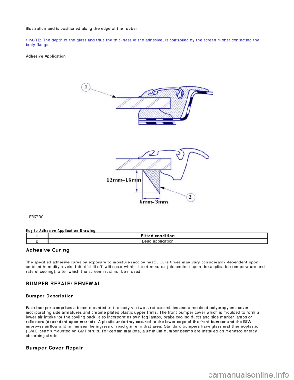
illustration and is positioned along the edge of the rubber.
• NOTE: The depth of the glass and thus the thickness of the ad hesive, is controlled by the screen rubber contacting the
body flange.
Adhesive Application
Key to Adhesive Application Drawing
Adhesive Curing
The specified adhesive cures by exposure to moisture (not by heat). Cure times may vary considerably dependent upon
ambient humidity levels. Initial 'chill off' will occur within 1 to 4 minutes ( dependent upon the application temperature and
rate of cooling), after which the screen must not be moved.
BUMPER REPAIR\RENEWAL
Bumper Description
Each bumper comprises a beam mounte d to the body via two strut assemblies and a moulded polypropylene cover
incorporating side armatures and chrome plated plastic upper trims. The front bumper cover which is moulded to form a
lower air intake for the cooling pack, also incorporates twin fog lamps, brake cooling ducts and side marker lamps or
reflectors (dependent upon market). A plastic undertray secured to the lower edge of the front bumper and the BIW
improves airflow and minimises the ingres s of road grime in that area. Standard bumpers have glass mat thermoplastic
(GMT) beams mounted on GMT struts. For certain markets, aluminium bumper beams are installed on menasco energy
absorbing struts.
Bumper Cover Repair
1Fitted condition
2Bead application
Page 2417 of 2490

Panels centered between two adjacent panels must have equal gaps on either side. For exceptions to this, refer to the
appropriate specification. Gaps between ad jacent panels or components must not expose harnesses, labels, brackets or
visually poor joint or assembly conditions.
• NOTE: Sliding roof panel clearances are specified without the edge seal installed.
Areas of particular concern are, fuel filler flap, trunk lid to fenders and saddle panels, hood to fenders, grill and headlamps,
sliding roof to main roof panel, door gaps at fenders, B\C posts, roof drip rail an d rocker panel, and bumper cover to fenders
and cross car assemblies
Alignment
Panels must be correctly profiled to maintain cosmetic appearance, and ensure co rrect seating of seals with minimal wind
noise. Areas of particular concern are hood to fenders, trunk lid to fenders and saddle panels, doors to apertures, doors to
fenders and adjacent doors and relationship of the sliding roof panel leading and trailing edges to the main roof panel.
Exterior Fitments
Bezels, trims and lamps must be concentric with apertu res and have equal clearances with adjacent panels.
Areas of particular concern are headlamp to hood, fender and trim panel, exhaust tailpipe trim to bumper cover cut-out,
rear lamp assembly to trunk lid, fender and bumper cover trim, and side feature lines including body side mouldings, fender
to door and door to door.
Exterior Clearances and Alignments-Front