1998 JAGUAR X308 oxygen
[x] Cancel search: oxygenPage 1177 of 2490
Th
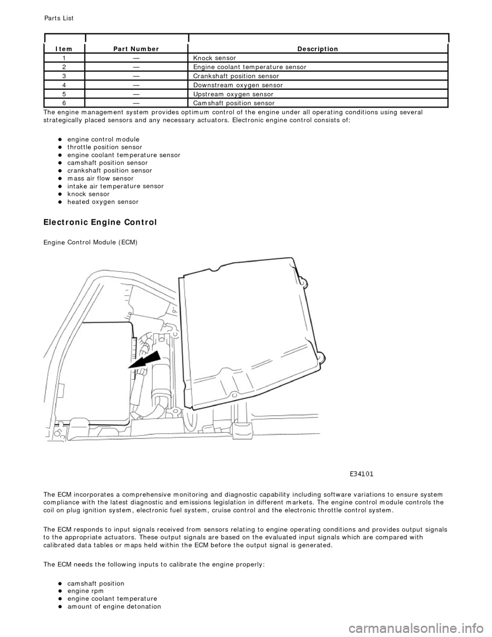
e engine management system provides optimum control of
the engine under all operating conditions using several
strategically placed sensors and any necessary actuators. Electronic engine control consists of:
engine
control module
throttle posi
tion sensor
engi
ne coolant temperature sensor
cam
shaft position sensor
c
rankshaft position sensor
mass air
flow sensor
intake air temper
ature sensor
kn
ock sensor
heat
ed oxygen sensor
Electronic Engine Control
Engine
Control Module (ECM)
The ECM incorporates a comprehensive monitoring and diagnostic capability including software variations to ensure system
compliance with the latest diagnostic and emissions legislation in different markets. The engine control module controls the
coil on plug ignition system, electronic fuel system, cr uise control and the electronic throttle control system.
The ECM responds to input signals received from sensors relating to engine operatin g conditions and provides output signals
to the appropriate actuators. These outp ut signals are based on the evaluated input signals which are compared with
calibrated data tables or maps held within th e ECM before the output signal is generated.
The ECM needs the following inputs to calibrate the engine properly:
cam
shaft position
It
em
Par
t Number
De
scription
1—Knock
sensor
2—Engine
coolant temperature sensor
3—Cranksh
aft position sensor
4—D
ownstream oxygen sensor
5—Upstream oxygen sensor
6—Camshaft position
sensor
P
arts List
engi
ne rpm
engi
ne coolant temperature
amount
of engine detonation
Page 1179 of 2490
generates a signal when th
e dr
ive plate passes the sensor
sen
ds the ECM signals indicating crankshaft position and engine speed
is e
ssential for calculating spark timing
En
gine Coolant Temperature (ECT) Sensor
sen
ds the ECM a signal indicating the temperature of the engine coolant
is a t
emperature dependent resistor with a negative temperature coefficient (resistance changes inversely with
respect to temperature) and is constantly monitored by the ECM
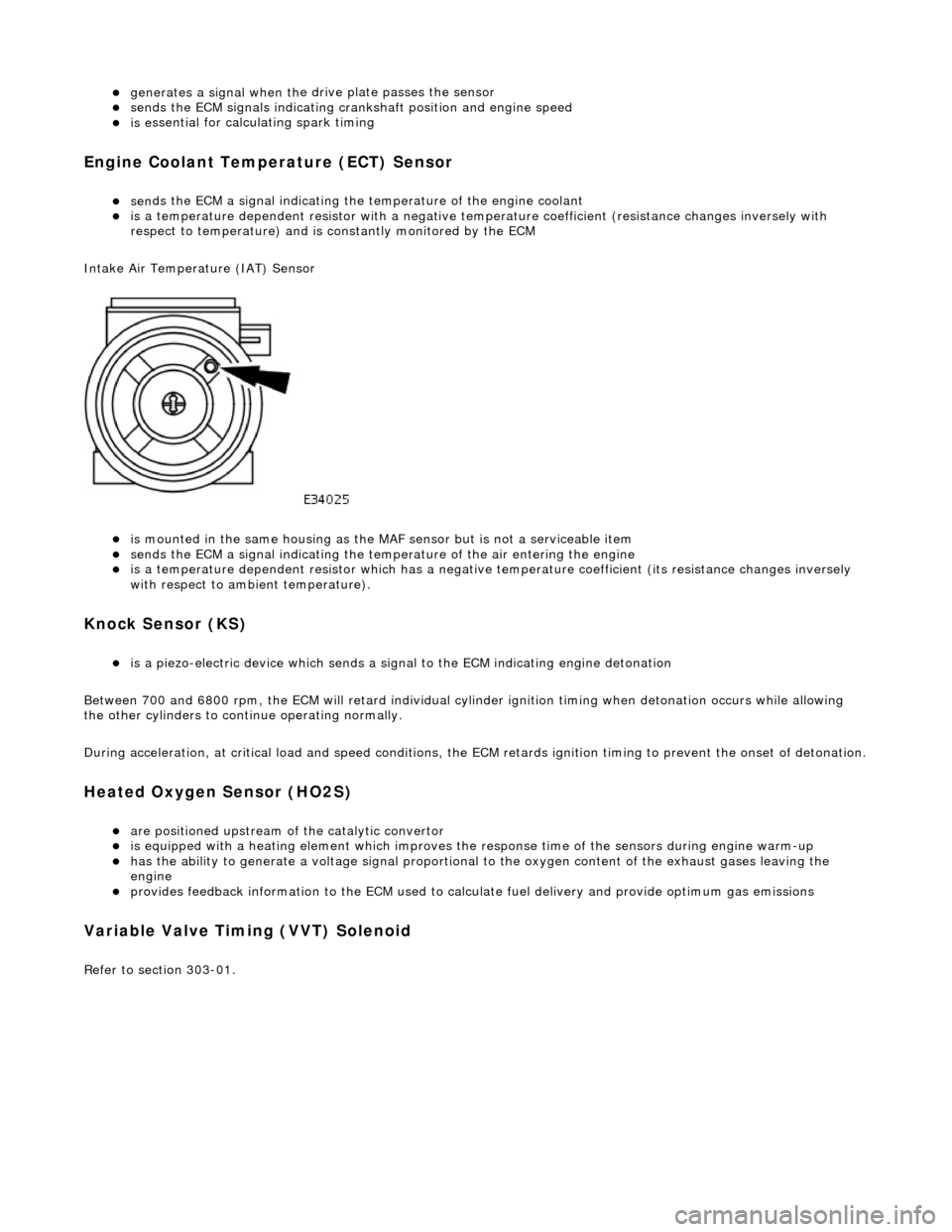
Intake Air Temperature (IAT) Sensor
is m
ounted in the same housing as the MA
F sensor but is not a serviceable item
sen
ds the ECM a signal indicating the temperature of the air entering the engine
is a t
emperature dependent resistor which has a negative
temperature coefficient (its resistance changes inversely
with respect to ambient temperature).
Knock S
ensor (KS)
is a pi
ezo-electric device which sends a signal
to the ECM indicating engine detonation
Between 700 and 6800 rpm, the ECM will retard individual cylinder ignition timing when detonation occurs while allowing
the other cylinders to continue operating normally.
During acceleration, at critical load and speed conditions, the ECM retards ignition timing to prevent the onset of detonation.
H
eated Oxygen Sensor (HO2S)
are
positioned upstream of the catalytic convertor
is equipped with
a heating element wh
ich improves the response time of the sensors during engine warm-up
h
as the ability to generate a voltage signal proportional to the oxygen content of the exhaust gases leaving the
engine
pr
ovides feedback information to the ECM used to calc
ulate fuel delivery and provide optimum gas emissions
Variable V
alve Timing (VVT) Solenoid
R
efer to section 303-01.
Page 1188 of 2490
It e
m
De
scr
iption
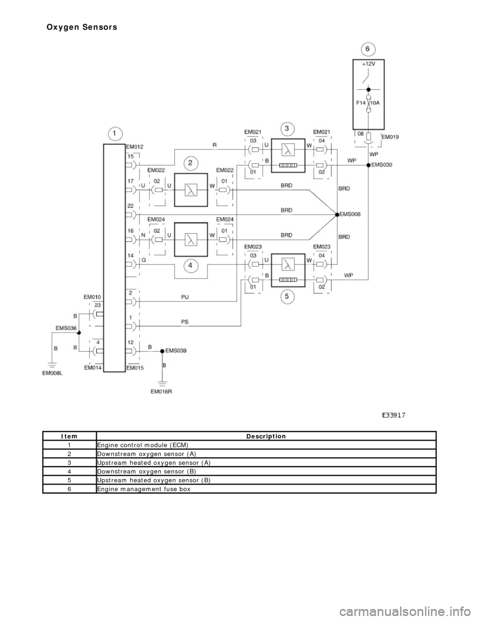
1Engine
c
ontrol
module (ECM)
2Do
wnstream oxygen sensor (A)
3Upstream heated ox
ygen sensor
(A)
4D
o
wnstream oxygen sensor (B)
5Upstream heated ox
ygen sensor (B)
6Engine
management fuse box
Ox
yg
en Sensors
Page 1211 of 2490
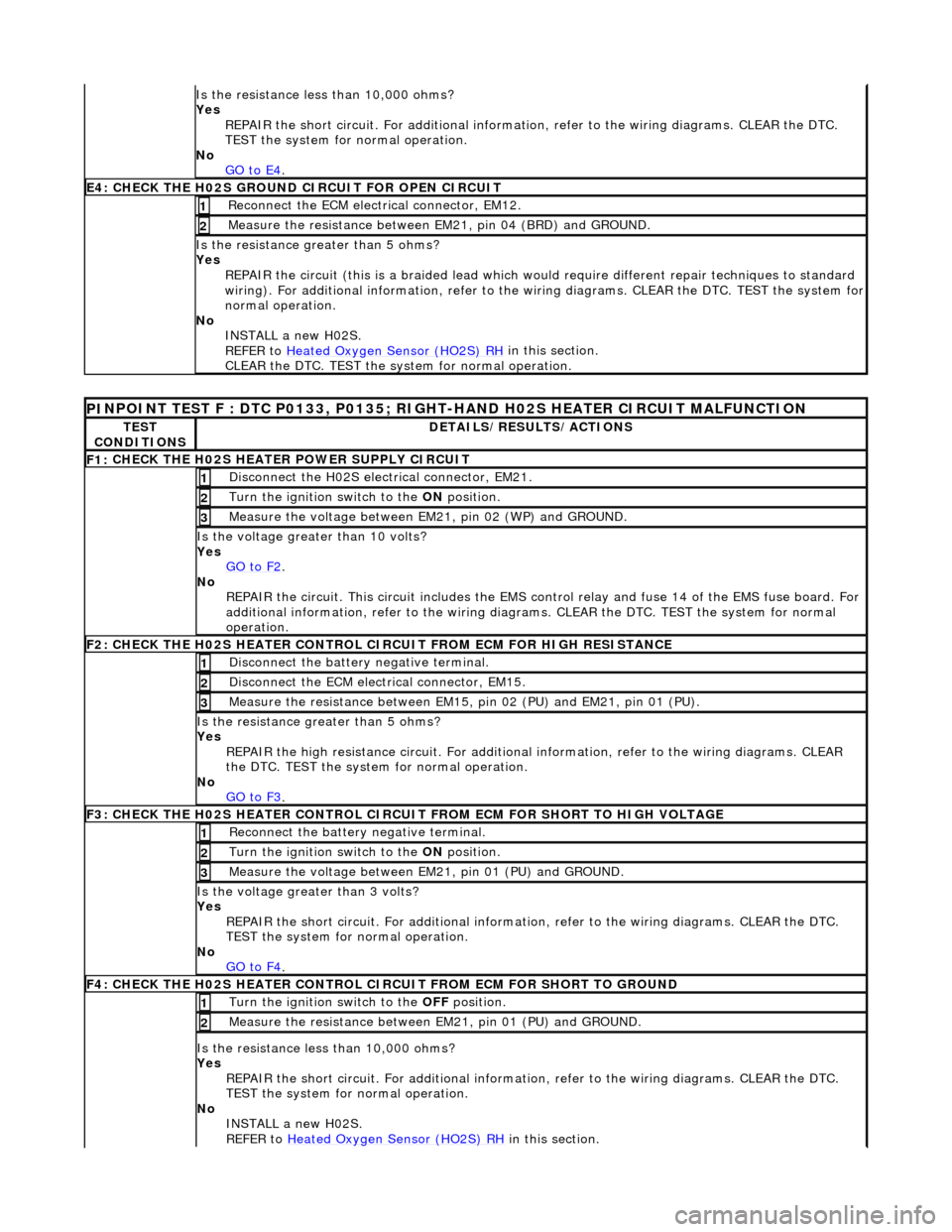
Is
the resistance less than 10,000 ohms?
Yes REPAIR the short circuit. For addi tional information, refer to the wiring diagrams. CLEAR the DTC.
TEST the system for normal operation.
No GO to E4
.
E4
: CHECK THE H02S GROUND
CIRCUIT FOR OPEN CIRCUIT
Re
connect the ECM electrical connector, EM12.
1
Meas
ure the resistance between EM21, pin 04 (BRD) and GROUND.
2
Is th
e resistance greater than 5 ohms?
Yes
REPAIR the circuit (this is a braide d lead which would require different repair techniques to standard
wiring). For additional information, refer to the wiring diagrams. CL EAR the DTC. TEST the system for
normal operation.
No INSTALL a new H02S.
REFER to Heated Oxygen Sensor (HO2S) RH
in this section.
CLEAR the DTC. TEST the syst em for normal operation.
PI
NPOINT TEST F : DTC P0133, P0135; RIGHT-HAND H02S HEATER CIRCUIT MALFUNCTION
TE
ST
CONDITIONS
D
ETAILS/RESULTS/ACTIONS
F1:
CHECK THE H02S HEATER POWER SUPPLY CIRCUIT
D
isconnect the H02S electrical connector, EM21.
1
Turn the ignition swi
tch to the ON
position.
2
Meas
ure the voltage between EM21, pin 02 (WP) and GROUND.
3
Is the vol
tage greater than 10 volts?
Yes GO to F2
.
No
REPAIR the circuit. This circuit in cludes the EMS control relay and fu se 14 of the EMS fuse board. For
additional information, refer to the wiring diagrams. CLEAR the DT C. TEST the system for normal
operation.
F2: CHECK THE H02
S HEATER CONTROL CI
RCUIT FROM ECM FOR HIGH RESISTANCE
Di
sconnect the battery negative terminal.
1
D
isconnect the ECM electrical connector, EM15.
2
Me
asure the resistance between EM15, pin 02 (PU) and EM21, pin 01 (PU).
3
Is th
e resistance greater than 5 ohms?
Yes REPAIR the high resistance circui t. For additional information, refer to the wiring diagrams. CLEAR
the DTC. TEST the system for normal operation.
No GO to F3
.
F3: CHECK THE H02
S HEATER CONTROL CIRCUI
T FROM ECM FOR SHORT TO HIGH VOLTAGE
R
econnect the battery negative terminal.
1
Turn the ignition swi
tch to the ON
position.
2
Meas
ure the voltage between EM21, pin 01 (PU) and GROUND.
3
Is th
e voltage greater than 3 volts?
Yes REPAIR the short circuit. For addi tional information, refer to the wiring diagrams. CLEAR the DTC.
TEST the system for normal operation.
No GO to F4
.
F4: CHECK THE H02
S HEATER CONTROL CI
RCUIT FROM ECM FOR SHORT TO GROUND
Turn the ignition swi
tch to the OFF
position.
1
Meas
ure the resistance between EM21, pin 01 (PU) and GROUND.
2
Is
the resistance less than 10,000 ohms?
Yes REPAIR the short circuit. For addi tional information, refer to the wiring diagrams. CLEAR the DTC.
TEST the system for normal operation.
No INSTALL a new H02S.
REFER to Heated Oxygen Sensor (HO2S) RH
in this section.
Page 1213 of 2490
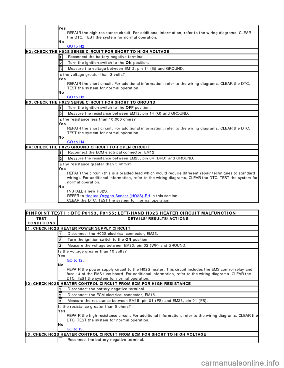
Yes
REPAIR the high resistance circui t. For additional information, refer to the wiring diagrams. CLEAR
the DTC. TEST the system for normal operation.
No GO to H2
.
H
2: CHECK THE H02S SENSE CIRCUIT FOR SHORT TO HIGH VOLTAGE
R
econnect the battery negative terminal.
1
Turn the ignition swi
tch to the ON
position.
2
M
easure the voltage between EM12, pin 14 (G) and GROUND.
3
Is th
e voltage greater than 3 volts?
Yes REPAIR the short circuit. For addi tional information, refer to the wiring diagrams. CLEAR the DTC.
TEST the system for normal operation.
No GO to H3
.
H
3: CHECK THE H02S SENSE CIRCUIT FOR SHORT TO GROUND
Turn the ignition swi
tch to the OFF
position.
1
Meas
ure the resistance between EM12, pin 14 (G) and GROUND.
2
Is
the resistance less than 10,000 ohms?
Yes REPAIR the short circuit. For addi tional information, refer to the wiring diagrams. CLEAR the DTC.
TEST the system for normal operation.
No GO to H4
.
H4:
CHECK THE H02S GROUND CIRCUIT FOR OPEN CIRCUIT
Re
connect the ECM electrical connector, EM12.
1
Meas
ure the resistance between EM23, pin 04 (BRD) and GROUND.
2
Is th
e resistance greater than 5 ohms?
Yes REPAIR the circuit (this is a braide d lead which would require different repair techniques to standard
wiring). For additional information, refer to the wiring diagrams. CL EAR the DTC. TEST the system for
normal operation.
No INSTALL a new H02S.
REFER to Heated Oxygen Sensor (HO2S) RH
in this section.
CLEAR the DTC. TEST the syst em for normal operation.
P
INPOINT TEST I : DTC P0153, P0155; LEFT-HAND H02S HEATER CIRCUIT MALFUNCTION
TE
ST
CONDITIONS
D
ETAILS/RESULTS/ACTIONS
I
1: CHECK H02S HEATER POWER SUPPLY CIRCUIT
D
isconnect the H02S electrical connector, EM23.
1
Turn the ignition swi
tch to the
ON position.
2
Meas
ure the voltage between EM23, pin 02 (WP) and GROUND.
3
Is the vol
tage greater than 10 volts?
Yes GO to I2
.
No
REPAIR the power supply circuit to the H02S heater. This circuit includes the EMS control relay and
fuse 14 of the EMS fuse board. For additional info rmation, refer to the wiring diagrams. CLEAR the
DTC. TEST the system for normal operation.
I
2: CHECK H02S HEATER CONTROL CIRC
UIT FROM ECM FOR HIGH RESISTANCE
Di
sconnect the battery negative terminal.
1
D
isconnect the ECM electrical connector, EM15.
2
Meas
ure the resistance between EM15,
pin 01 (PS) and EM23, pin 01 (PS).
3
Is th
e resistance greater than 5 ohms?
Yes REPAIR the high resistance circuit. For additional information, refer to the wiring diagrams. CLEAR the
DTC. TEST the system for normal operation.
No GO to I3
.
I
3: CHECK H02S HEATER CONTROL CIRCUIT
FROM ECM FOR SHORT TO HIGH VOLTAGE
R
econnect the battery negative terminal.
Page 1214 of 2490
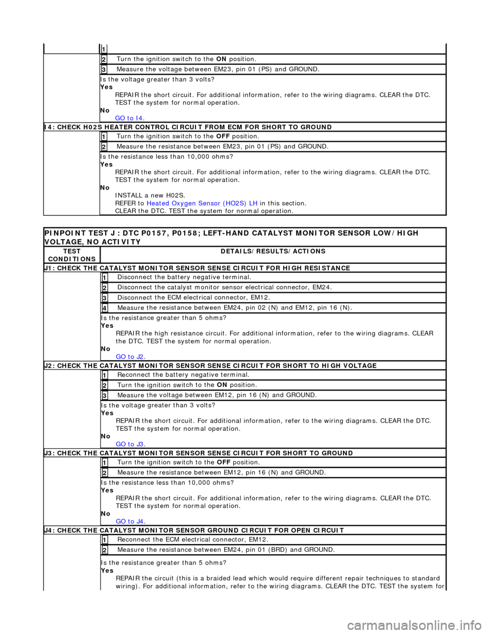
1
Turn the ignition swit
ch to the
ON position.
2
Meas ure t
he voltage between EM23, pin 01 (PS) and GROUND.
3
Is th
e volt
age greater than 3 volts?
Yes REPAIR the short circuit. For addi tional information, refer to the wiring diagrams. CLEAR the DTC.
TEST the system for normal operation.
No GO to I4
.
I4
: CHECK H02S HEATER CONTROL CIRCUIT FROM ECM FOR SHORT TO GROUND
Turn the ignition swit
ch to the
OFF position.
1
Measure t
he resistance between EM23, pin 01 (PS) and GROUND.
2
Is t
he resistance less than 10,000 ohms?
Yes REPAIR the short circuit. For addi tional information, refer to the wiring diagrams. CLEAR the DTC.
TEST the system for normal operation.
No INSTALL a new H02S.
REFER to Heated Oxygen Sensor (HO2S) LH
in this
section.
CLEAR the DTC. TEST the system for normal operation.
P INPOINT TES
T J : DTC P0157, P0158; LEFT-H
AND CATALYST MONITOR SENSOR LOW/HIGH
VOLTAGE, NO ACTIVITY
TE S
T
CONDITIONS
D E
TAILS/RESULTS/ACTIONS
J
1
: CHECK THE CATALYST MONITOR SENSOR
SENSE CIRCUIT FOR HIGH RESISTANCE
Disc
onnect the battery negative terminal.
1
Di
sc
onnect the catalyst monitor sensor electrical connector, EM24.
2
Disc
onne
ct the ECM electrical connector, EM12.
3
Meas
ure t
he resistance between EM24, pin 02 (N) and EM12, pin 16 (N).
4
Is th
e res
istance greater than 5 ohms?
Yes REPAIR the high resistance circui t. For additional information, refer to the wiring diagrams. CLEAR
the DTC. TEST the system for normal operation.
No GO to J2
.
J2
: CHECK THE CATALYST MONITOR SENSOR SENSE CIRCUIT FOR SHORT TO HIGH VOLTAGE
R
e
connect the battery negative terminal.
1
Turn the ignition swi
t
ch to the ON
position.
2
Measure t
he voltage between EM12, pin 16 (N) and GROUND.
3
Is th
e volt
age greater than 3 volts?
Yes REPAIR the short circuit. For addi tional information, refer to the wiring diagrams. CLEAR the DTC.
TEST the system for normal operation.
No GO to J3
.
J3
: CHECK THE CATALYST MONITOR SENSOR
SENSE CIRCUIT FOR SHORT TO GROUND
Turn the ignition swit
ch to the OFF
position.
1
Measure t
he resistance between EM12, pin 16 (N) and GROUND.
2
Is t
he resistance less than 10,000 ohms?
Yes REPAIR the short circuit. For addi tional information, refer to the wiring diagrams. CLEAR the DTC.
TEST the system for normal operation.
No GO to J4
.
J4
: CHECK THE CATALYST MONITOR SENSOR
GROUND CIRCUIT FOR OPEN CIRCUIT
Reconn
ect the ECM electrical connector, EM12.
1
Meas
ure t
he resistance between EM24, pin 01 (BRD) and GROUND.
2
Is th
e res
istance greater than 5 ohms?
Yes REPAIR the circuit (this is a braide d lead which would require different repair techniques to standard
wiring). For additional information, refer to the wiring diagrams. CL EAR the DTC. TEST the system for
Page 1249 of 2490
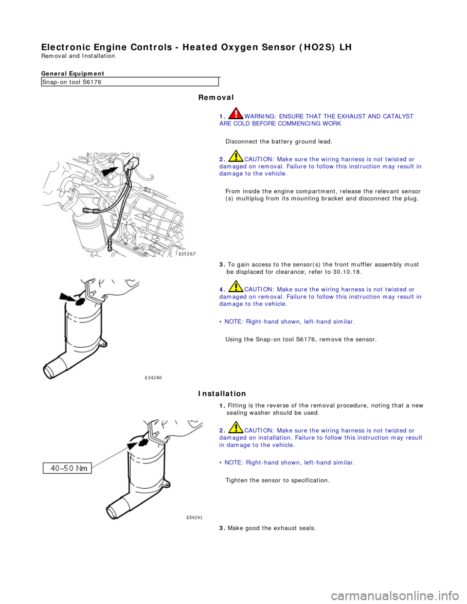
Electron
ic Engine Controls -
Heated Oxygen Sensor (HO2S) LH
Rem
oval and Installation
General Equipment
Remov
al
Installation
Snap
-on tool S6176
1. WARNING: ENSURE THAT TH E EXHAUST AND CATALYST
ARE COLD BEFORE COMMENCING WORK
Disconnect the battery ground lead.
2.
CAUTION: Make sure the wiring harness is not twisted or
damaged on removal. Failure to follow this instruction may result in
damage to the vehicle.
From inside the engine compartm ent, release the relevant sensor
(s) multiplug from its mounting bracket and disconnect the plug.
3.
To gain access to the sensor(s) the front muffler assembly must
be displaced for clearance; refer to 30.10.18.
4.
CAUTION: Make sure the wiring harness is not twisted or
damaged on removal. Failure to follow this instruction may result in
damage to the vehicle.
• NOTE: Right-hand shown, left-hand similar.
Using the Snap-on tool S6176, remove the sensor.
1.
Fitting is the reverse of the remo val procedure, noting that a new
sealing washer should be used.
2.
CAUTION: Make sure the wiring harness is not twisted or
damaged on installation. Failure to follow this instruction may result
in damage to the vehicle.
• NOTE: Right-hand shown, left-hand similar.
Tighten the sensor to specification.
3.
Make good the exhaust seals.
Page 1250 of 2490
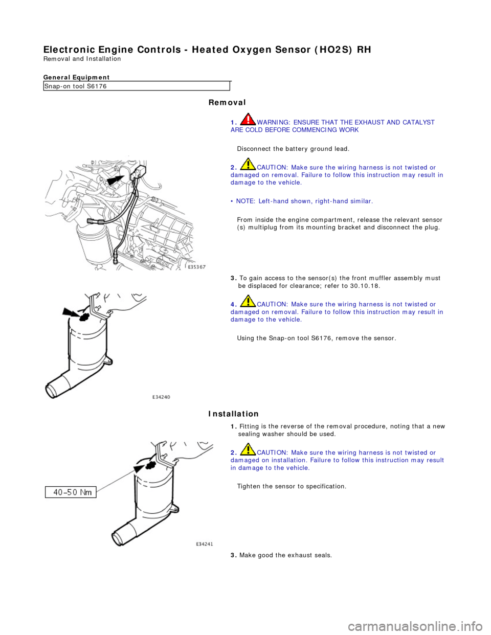
Electronic
Engine Controls -
Heated Oxygen Sensor (HO2S) RH
Remo
val and Installation
General Equipment
Remov a
l
Installation
Snap -on to
ol S6176
1. WARNING: ENSURE THAT TH E EXHAUST AND CATALYST
ARE COLD BEFORE COMMENCING WORK
Disconnect the battery ground lead.
2. CAU
TION: Make sure the wiring harness is not twisted or
damaged on removal. Failure to follow this instruction may result in
damage to the vehicle.
• NOTE: Left-hand shown, right-hand similar.
From inside the engine compartm ent, release the relevant sensor
(s) multiplug from its mounting bracket and disconnect the plug.
3. To
gain access to the sensor(s)
the front muffler assembly must
be displaced for clearance; refer to 30.10.18.
4. CAU
TION: Make sure the wiring harness is not twisted or
damaged on removal. Failure to follow this instruction may result in
damage to the vehicle.
Using the Snap-on tool S6176, remove the sensor.
1. Fittin
g is the reverse of the remo
val procedure, noting that a new
sealing washer should be used.
2. CAU
TION: Make sure the wiring harness is not twisted or
damaged on installation. Failure to follow this instruction may result
in damage to the vehicle.
Tighten the sensor to specification.
3. M
ake good the exhaust seals.