Page 1395 of 2490
and/or increased performance as appropriate.
Serial Communications Interfaces
Controller Area Network (CAN)
The TCM is an integral part of the CAN system which facilita tes the interchange of real-time data between control modules
and sensors; refer to 303-14 fo r a full description of CAN.
Transmission Pressure Regulators and Shift Solenoids Circuit Diagram
ItemPart NumberDescription
1—Transmission oil temperature sensor
2—Switch
3—Shift solenoid 1 <-> 2, 4 <-> 5
4—Shift solenoid 2 <-> 3
Page 1761 of 2490

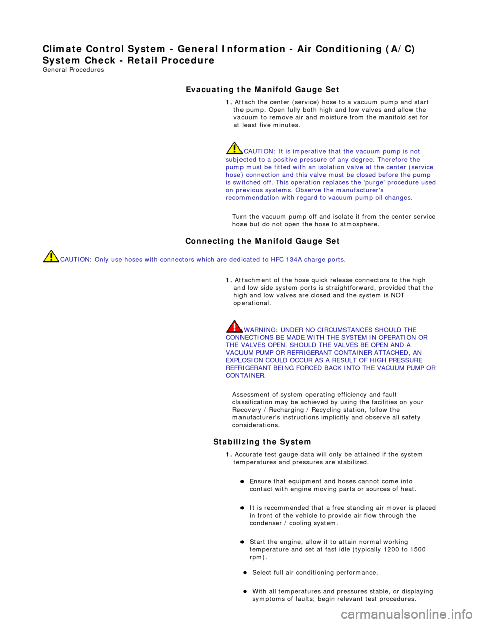
Climate Co
ntrol System - General In
formation - Air Conditioning (A/C)
System Check - Re tail Procedure
Gen
eral Procedures
E
vacuating the Manifold Gauge Set
Connecting the Manifold Gauge Set
C
AUTION: Only use hoses with connectors wh
ich are dedicated to HFC 134A charge ports.
Stabilizing the System
1.
At
tach the center (service) hose to a vacuum pump and start
the pump. Open fully both high and low valves and allow the
vacuum to remove air and mois ture from the manifold set for
at least five minutes.
CAUTION: It is imperative th at the vacuum pump is not
subjected to a positi ve pressure of any degree. Therefore the
pump must be fitted wi th an isolation valve at the center (service
hose) connection and this valve mu st be closed before the pump
is switched off. This operation replaces the 'purge' procedure used
on previous systems. Observe the manufacturer's
recommendation with regard to vacuum pump oil changes.
Turn the vacuum pump off and isol ate it from the center service
hose but do not open the hose to atmosphere.
1. Att
achment of the hose quick release connectors to the high
and low side system ports is stra ightforward, provided that the
high and low valves are closed and the system is NOT
operational.
WARNING: UNDER NO CIRCUMSTANCES SHOULD THE
CONNECTIONS BE MADE WITH THE SYSTEM IN OPERATION OR
THE VALVES OPEN. SHOULD THE VALVES BE OPEN AND A
VACUUM PUMP OR REFRIGERANT CONTAINER ATTACHED, AN
EXPLOSION COULD OCCUR AS A RESULT OF HIGH PRESSURE
REFRIGERANT BEING FORCED BACK INTO THE VACUUM PUMP OR
CONTAINER.
Assessment of system operating efficiency and fault
classification may be achieved by using the facilities on your
Recovery / Recharging / Recycling station, follow the
manufacturer's instructions implicitly and observe all safety
considerations.
1. Accurate test gauge data wi
ll on
ly be attained if the system
temperatures and pressures are stabilized.
E
nsure that equipment and hoses cannot come into
contact with engine moving parts or sources of heat.
It is recommended th at a free standing air
mover is placed
in front of the vehicle to provide air flow through the
condenser / cooling system.
St
art the engine, allow it to attain normal working
temperature and set at fast idle (typically 1200 to 1500
rpm).
Select full
air condit
ioning performance.
With
all temperatures and pres
sures stable, or displaying
symptoms of faults; begin relevant test procedures.
Page 2019 of 2490

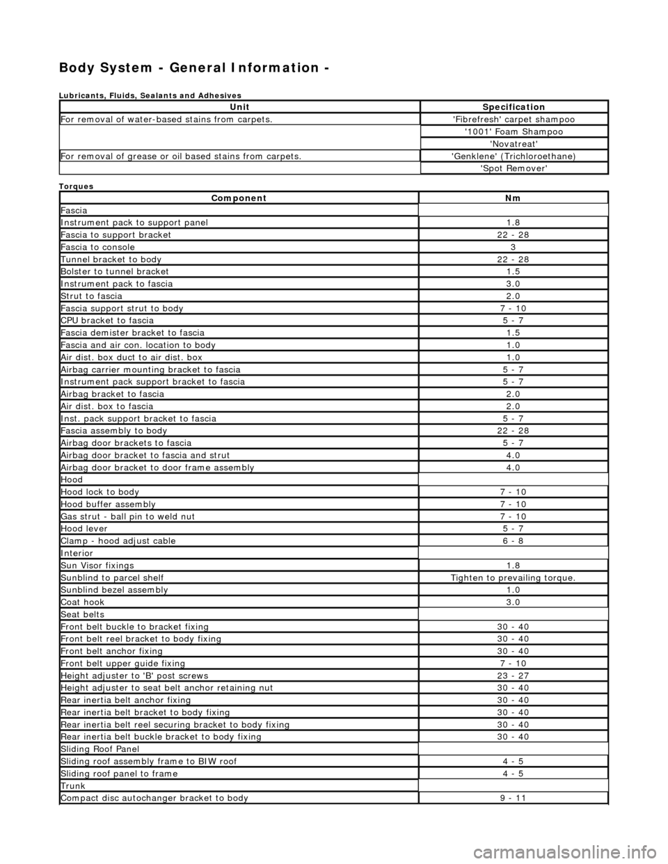
Body System - General Information -
Lubricants, Fluids, Sealants and Adhesives
Torques
UnitSpecification
For removal of water-based stains from carpets.'Fibrefresh' carpet shampoo
'1001' Foam Shampoo
'Novatreat'
For removal of grease or oil based stains from carpets.'Genklene' (Trichloroethane)
'Spot Remover'
ComponentNm
Fascia
Instrument pack to support panel1.8
Fascia to support bracket22 - 28
Fascia to console3
Tunnel bracket to body22 - 28
Bolster to tunnel bracket1.5
Instrument pack to fascia3.0
Strut to fascia2.0
Fascia support strut to body7 - 10
CPU bracket to fascia5 - 7
Fascia demister bracket to fascia1.5
Fascia and air con. location to body1.0
Air dist. box duct to air dist. box1.0
Airbag carrier mounting bracket to fascia5 - 7
Instrument pack suppo rt bracket to fascia5 - 7
Airbag bracket to fascia2.0
Air dist. box to fascia2.0
Inst. pack support bracket to fascia5 - 7
Fascia assembly to body22 - 28
Airbag door brackets to fascia5 - 7
Airbag door bracket to fascia and strut4.0
Airbag door bracket to door frame assembly4.0
Hood
Hood lock to body7 - 10
Hood buffer assembly7 - 10
Gas strut - ball pin to weld nut7 - 10
Hood lever5 - 7
Clamp - hood adjust cable6 - 8
Interior
Sun Visor fixings1.8
Sunblind to parcel shelfTighten to prevailing torque.
Sunblind bezel assembly1.0
Coat hook3.0
Seat belts
Front belt buckle to bracket fixing30 - 40
Front belt reel bracket to body fixing30 - 40
Front belt anchor fixing30 - 40
Front belt upper guide fixing7 - 10
Height adjuster to 'B' post screws23 - 27
Height adjuster to seat belt anchor retaining nut30 - 40
Rear inertia belt anchor fixing30 - 40
Rear inertia belt bracket to body fixing30 - 40
Rear inertia belt reel secu ring bracket to body fixing30 - 40
Rear inertia belt buckle bracket to body fixing30 - 40
Sliding Roof Panel
Sliding roof assembly frame to BIW roof4 - 5
Sliding roof panel to frame4 - 5
Trunk
Compact disc autochanger bracket to body9 - 11