1998 JAGUAR X308 clutch
[x] Cancel search: clutchPage 1263 of 2490
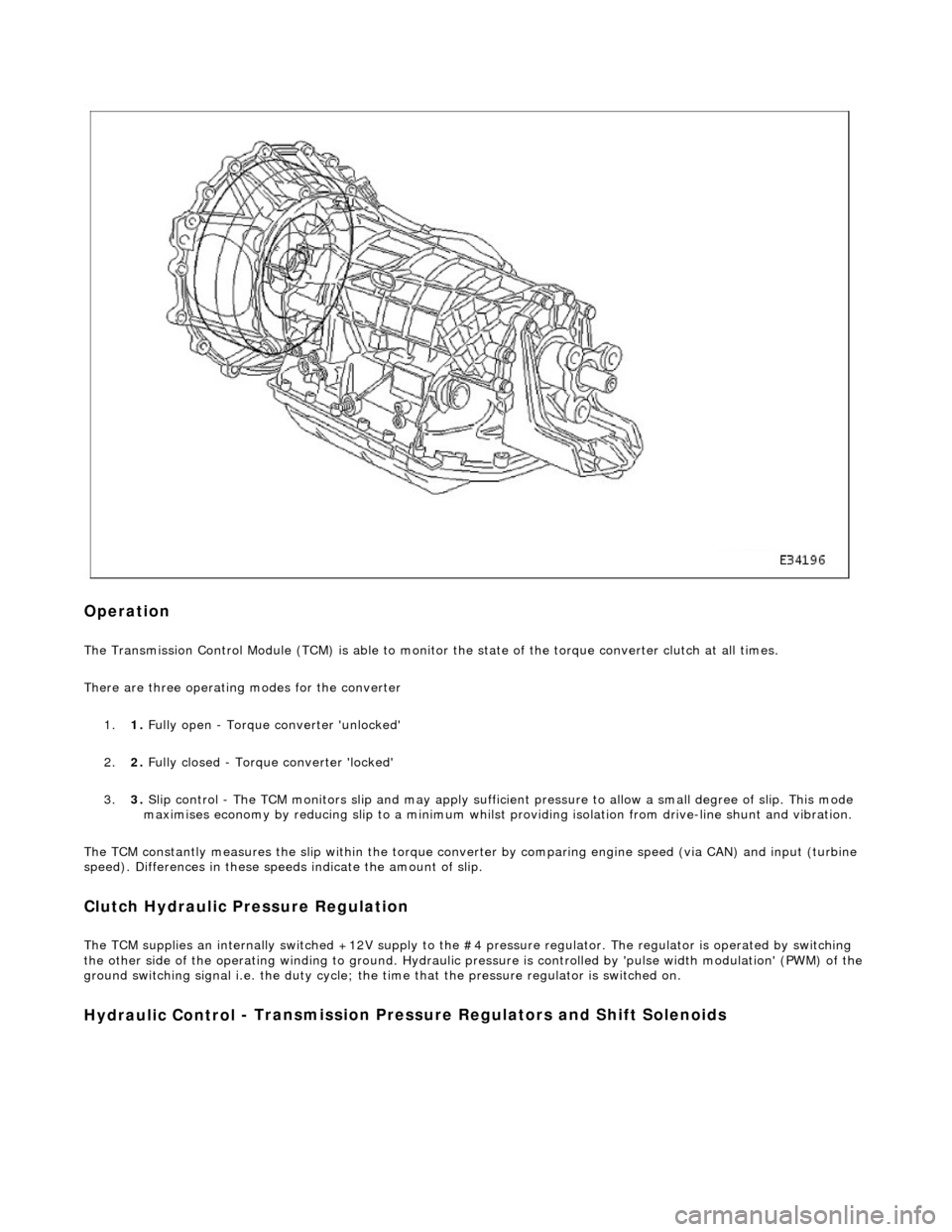
Op
eration
The T
ransmission Control Module (TCM) is
able to monitor the state of the torque converter clut ch at all times.
There are three operating modes for the converter
1. 1. Fully open - Torque converter 'unlocked'
2. 2. Fully closed - Torque converter 'locked'
3. 3. Slip control - The TCM monitors slip and may apply sufficie nt pressure to allow a small degree of slip. This mode
maximises economy by reducing slip to a minimum whilst providing isolation from drive-line shunt and vibration.
The TCM constantly measures the slip within the torque conver ter by comparing engine speed (via CAN) and input (turbine
speed). Differences in these speeds indicate the amount of slip.
Clutch Hydraulic Pressure Regulation
The T
CM supplies an internally switched +1
2V supply to the #4 pressure regulator. The regulator is operated by switching
the other side of the operating winding to ground. Hydraulic pressure is controlled by 'pulse width modulation' (PWM) of the
ground switching signal i.e. the duty cycle; the time that the pressure regulator is switched on.
Hydraulic Control
- Transmission Pre
ssure Regulators an d Shift Solenoids
Page 1268 of 2490
Input speed is monitored by the TCM with a rationality check being made against output speed. A fault will be flagged if the
indicated input speed exceeds 7400 rpm. Additionally, a failure judgement will be made if the indicated input speed is <160
rpm with engine speed >608 rpm and output speed >224 rpm
The procedure is similar for the output sp eed diagnostic. A fault (non OBDII) will be flagged if the indicated input speed
exceeds 6712 rpm. Additionally a failure judgement will be ma de if the indicated output speed is <160 rpm and the average
road wheel speed exceeds 100 rpm.
Under normal circumstance s after the output speed diagnost ic fault code has been set, the TCM uses rear wheel speed
information to compute its calculations, this has no effect on transmission operation. However, should a second fault occur,
in the ABS system, thus making rear wheel speed information unavailable, an additional fault code will be logged.
Control Systems
Introduction
Gear selection is achieved by controlling the flow of transmission fluid to internal multi-disc clutches.
The three solenoid valves direct the transmission fluid flow to the selected clutches and the pressure regulators control the
fluid pressure to each component. One pr essure regulator serves as a master pressure control for the entire system and a
second is used exclusively for torque converter clutch lock-up operation.
The TCM controls the internal components thus determining gear selection and shift pattern.
In the event of an electronic system fault the basic function s Park, Reverse Neutral and Drive Fourth are retained by the
hydraulic system.
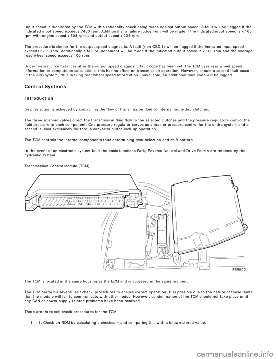
Transmission Control Module (TCM)
The TCM is located in the same housing as th e ECM and is accessed in the same manner.
The TCM performs several 'self check' procedur es to ensure correct operation. It is possible due to the nature of these faults
that the module will fail to communicate with other nodes. However, condemnation of the TCM should not take place until
any CAN or power supply related problems have been resolved.
There are three self check procedures for the TCM. 1. 1. Check on ROM by calculatin
g a checksum and comparing this with a known stored value.
Page 1276 of 2490
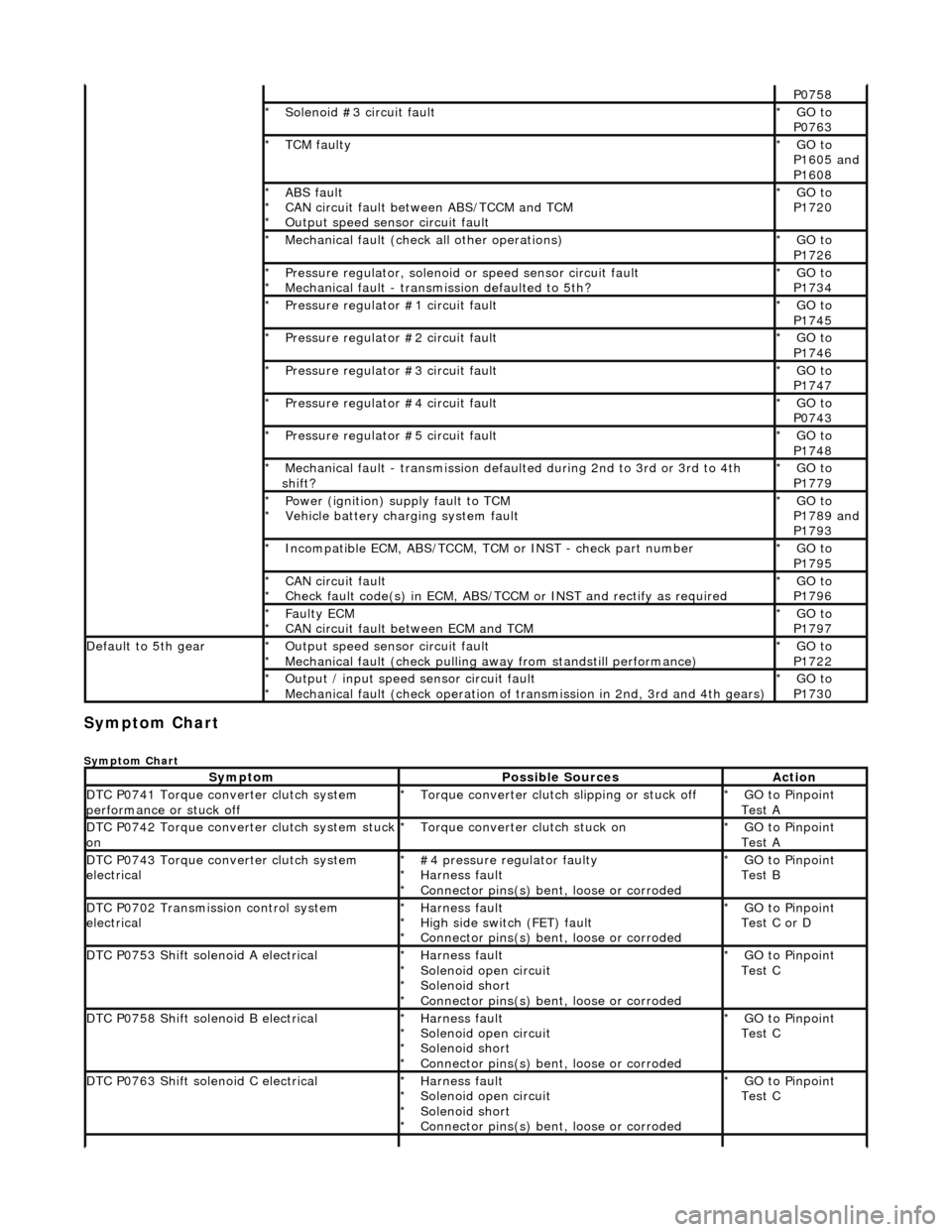
Symptom Chart
Symptom Chart
P0758
Solenoid #3 circuit fault
*GO to
P0763
*
TCM faulty
*GO to
P1605 and
P1608
*
ABS fault
CAN circuit fault between ABS/TCCM and TCM
Output speed sensor circuit fault
*
*
*GO to
P1720
*
Mechanical fault (check all other operations)
*GO to
P1726
*
Pressure regulator, solenoid
or speed sensor circuit fault
Mechanical fault - transmission defaulted to 5th?
*
*GO to
P1734
*
Pressure regulator #1 circuit fault
*GO to
P1745
*
Pressure regulator #2 circuit fault
*GO to
P1746
*
Pressure regulator #3 circuit fault
*GO to
P1747
*
Pressure regulator #4 circuit fault
*GO to
P0743
*
Pressure regulator #5 circuit fault
*GO to
P1748
*
Mechanical fault - transmission defaul
ted during 2nd to 3rd or 3rd to 4th
shift?
*GO to
P1779
*
Power (ignition) supply fault to TCM
Vehicle battery charging system fault
*
*GO to
P1789 and
P1793
*
Incompatible ECM, ABS/TCCM, TCM or INST - check part number
*GO to
P1795
*
CAN circuit fault
Check fault code(s) in ECM, ABS/TCCM or INST and rectify as required
*
*GO to
P1796
*
Faulty ECM
CAN circuit fault between ECM and TCM
*
*GO to
P1797
*
Default to 5th gearOutput speed sensor circuit fault
Mechanical fault (check pulling
away from standstill performance)
*
*GO to
P1722
*
Output / input speed sensor circuit fault
Mechanical fault (check operation of tr
ansmission in 2nd, 3rd and 4th gears)
*
*GO to
P1730
*
SymptomPossible SourcesAction
DTC P0741 Torque converter clutch system
performance or stuck offTorque converter clutch slipping or stuck off
*GO to Pinpoint
Test A
*
DTC P0742 Torque converter clutch system stuck onTorque converter clutch stuck on
*GO to Pinpoint
Test A
*
DTC P0743 Torque converter clutch system
electrical#4 pressure regulator faulty
Harness fault
Connector pins(s) bent
, loose or corroded
*
*
*GO to Pinpoint
Test B
*
DTC P0702 Transmission control system
electricalHarness fault
High side switch (FET) fault
Connector pins(s) bent
, loose or corroded
*
*
*GO to Pinpoint
Test C or D
*
DTC P0753 Shift solenoid A electricalHarness fault
Solenoid open circuit
Solenoid short
Connector pins(s) bent
, loose or corroded
*
*
*
*GO to Pinpoint
Test C
*
DTC P0758 Shift solenoid B electricalHarness fault
Solenoid open circuit
Solenoid short
Connector pins(s) bent
, loose or corroded
*
*
*
*GO to Pinpoint
Test C
*
DTC P0763 Shift solenoid C electricalHarness fault
Solenoid open circuit
Solenoid short
Connector pins(s) bent
, loose or corroded
*
*
*
*GO to Pinpoint
Test C
*
Page 1277 of 2490
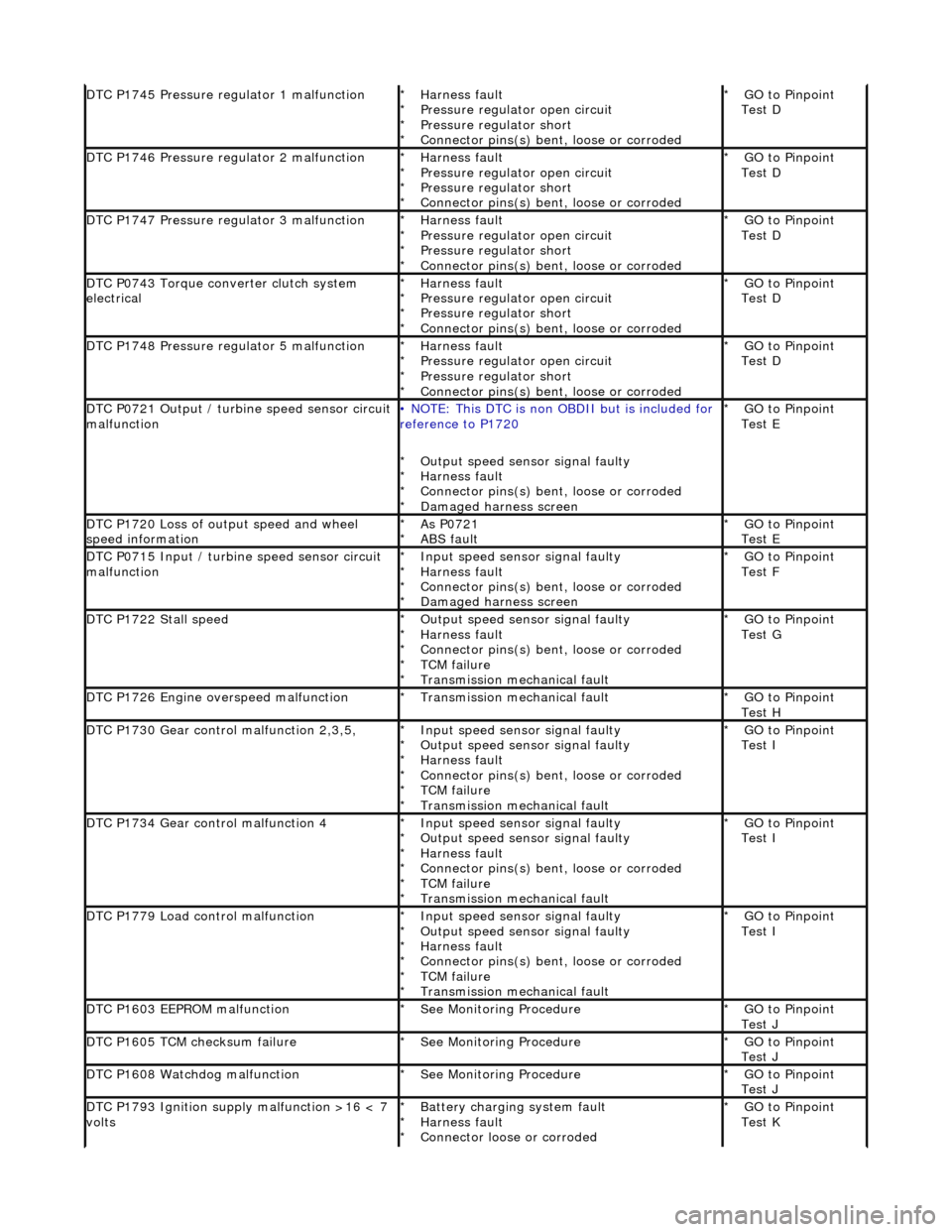
DTC P1745 Pressure regulator 1 malfunctionHarness fault
Pressure regulator open circuit
Pressure regulator short
Connector pins(s) bent, loose or corroded
*
*
*
*GO to Pinpoint
Test D
*
DTC P1746 Pressure regulator 2 malfunctionHarness fault
Pressure regulator open circuit
Pressure regulator short
Connector pins(s) bent
, loose or corroded
*
*
*
*GO to Pinpoint
Test D
*
DTC P1747 Pressure regulator 3 malfunctionHarness fault
Pressure regulator open circuit
Pressure regulator short
Connector pins(s) bent
, loose or corroded
*
*
*
*GO to Pinpoint
Test D
*
DTC P0743 Torque converter clutch system
electricalHarness fault
Pressure regulator open circuit
Pressure regulator short
Connector pins(s) bent
, loose or corroded
*
*
*
*GO to Pinpoint
Test D
*
DTC P1748 Pressure regulator 5 malfunctionHarness fault
Pressure regulator open circuit
Pressure regulator short
Connector pins(s) bent
, loose or corroded
*
*
*
*GO to Pinpoint
Test D
*
DTC P0721 Output / turbine speed sensor circuit
malfunction• NOTE: This DTC is non OBDII but is included for
reference to P1720
Output speed sensor signal faulty
Harness fault
Connector pins(s) bent , loose or corroded
Damaged harness screen
*
*
*
*GO to Pinpoint
Test E
*
DTC P1720 Loss of output speed and wheel
speed informationAs P0721
ABS fault
*
*GO to Pinpoint
Test E
*
DTC P0715 Input / turbine speed sensor circuit
malfunctionInput speed sensor signal faulty
Harness fault
Connector pins(s) bent
, loose or corroded
Damaged harness screen
*
*
*
*GO to Pinpoint
Test F
*
DTC P1722 Stall speedOutput speed sensor signal faulty
Harness fault
Connector pins(s) bent
, loose or corroded
TCM failure
Transmission mechanical fault
*
*
*
*
*GO to Pinpoint
Test G
*
DTC P1726 Engine overspeed malfunctionTransmission mechanical fault
*GO to Pinpoint
Test H
*
DTC P1730 Gear control malfunction 2,3,5,Input speed sensor signal faulty
Output speed sensor signal faulty
Harness fault
Connector pins(s) bent
, loose or corroded
TCM failure
Transmission mechanical fault
*
*
*
*
*
*GO to Pinpoint
Test I
*
DTC P1734 Gear control malfunction 4Input speed sensor signal faulty
Output speed sensor signal faulty
Harness fault
Connector pins(s) bent
, loose or corroded
TCM failure
Transmission mechanical fault
*
*
*
*
*
*GO to Pinpoint
Test I
*
DTC P1779 Load control malfunctionInput speed sensor signal faulty
Output speed sensor signal faulty
Harness fault
Connector pins(s) bent
, loose or corroded
TCM failure
Transmission mechanical fault
*
*
*
*
*
*GO to Pinpoint
Test I
*
DTC P1603 EEPROM malfunctionSee Monitoring Procedure
*GO to Pinpoint
Test J
*
DTC P1605 TCM checksum failureSee Monitoring Procedure
*GO to Pinpoint
Test J
*
DTC P1608 Watchdog malfunctionSee Monitoring Procedure
*GO to Pinpoint
Test J
*
DTC P1793 Ignition supply malfunction >16 < 7
voltsBattery charging system fault
Harness fault
Connector loose or corroded
*
*
*GO to Pinpoint
Test K
*
Page 1390 of 2490
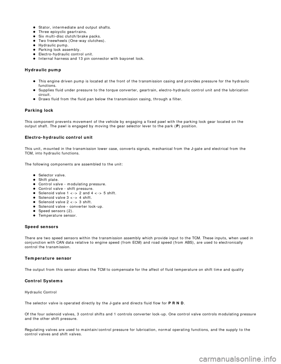
Stator, intermediate and output shafts. Three epicyclic geartrains. Six multi-disc clutch/brake packs. Two freewheels (One-way clutches). Hydraulic pump. Parking lock assembly. Electro-hydraulic control unit. Internal harness and 13 pin connector with bayonet lock.
Hydraulic pump
This engine driven pump is located at the front of the transmission casing and provides pressure for the hydraulic
functions.
Supplies fluid under pressure to the torq ue converter, geartrain, electro-hydraulic control unit and the lubrication
circuit.
Draws fluid from the fluid pa n below the transmission casing, through a filter.
Parking lock
This component prevents movement of th e vehicle by engaging a fixed pawl with the parking lock gear located on the
output shaft. The pawl is engaged by movi ng the gear selector lever to the park (P) position.
Electro-hydraulic control unit
This unit, mounted in the transmission lower case, converts signals, mechanical from the J-gate and electrical from the
TCM, into hydraulic functions.
The following components ar e assembled to the unit:
Selector valve. Shift plate. Control valve - modulating pressure. Control valve - shift pressure. Solenoid valve 1 <-> 2 and 4 <-> 5 shift. Solenoid valve 3 <-> 4 shift. Solenoid valve 2 <-> 3 shift. Solenoid valve - converter lock-up. Speed sensors (2). Temperature sensor.
Speed sensors
There are two speed sensors within the transmission assembly which provide input to the TCM. These inputs, when used in
conjunction with CAN data relative to engine speed (from ECM) and road speed (from ABS), are used to electronically
control the transmission.
Temperature sensor
The output from this sensor allows the TCM to compensate for the affect of fluid temperature on shift time and quality
Control Systems
Hydraulic Control
The selector valve is operated directly by the J-gate and directs fluid flow for P R N D.
Of the four solenoid valves, 3 control shifts and 1 controls converter lock-up. One control valve controls modulating pressure
and the other shift pressure.
Regulating valves are used to maintain/control pressure for lu brication, normal operating functions, and the supply to the
control valves and shift valves.
Page 1392 of 2490
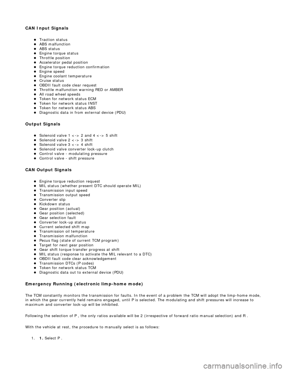
CAN Input Signals
Traction status ABS malfunction ABS status Engine torque status Throttle position Accelerator pedal position Engine torque reduction confirmation Engine speed Engine coolant temperature Cruise status OBDII fault code clear request Throttle malfunction warning RED or AMBER All road wheel speeds Token for network status ECM Token for network status INST Token for network status ABS Diagnostic data in from external device (PDU)
Output Signals
Solenoid valve 1 <-> 2 and 4 <-> 5 shift Solenoid valve 2 <-> 3 shift Solenoid valve 3 <-> 4 shift Solenoid valve converter lock-up clutch Control valve - modulating pressure Control valve - shift pressure
CAN Output Signals
Engine torque reduction request MIL status (whether present DTC should operate MIL) Transmission input speed Transmission output speed Converter slip Kickdown status Gear position (actual) Gear position (selected) Gear selection fault Converter lock-up status Current selected shift map Transmission oil temperature Transmission malfunction Pecus flag (state of current TCM program) Target for next gear position Gear shift torque transfer progress at shift MIL status (response to activate the MIL relevant to a DTC) OBDII fault code clear acknowledgement Transmission DTCs (P codes) Token for network status TCM Diagnostic data out to external device (PDU)
Emergency Running (elect ronic limp-home mode)
The TCM constantly monitors the transmissi on for faults. In the event of a problem the TCM will adopt the limp-home mode, in which the gear currently held remains engaged, until P is selected. The modulati ng and shift pressures will increase to
maximum and converter lock-up will be inhibited.
Following the selection of P , the only ratios available will be 2 (irrespective of forward ratio manual selection) and R .
With the vehicle at rest, the procedure to manually select is as follows:
1. 1. Select P .
Page 1400 of 2490
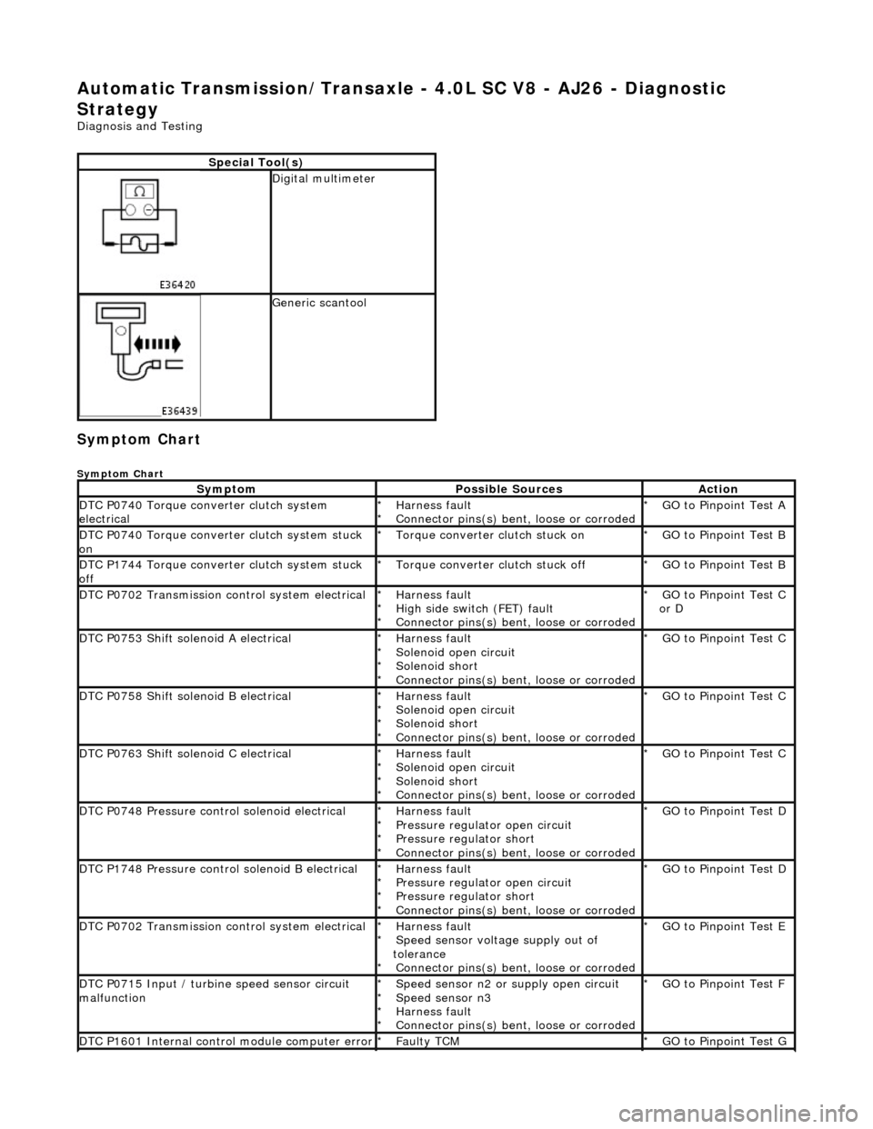
Automatic Transmission/Transaxle - 4.0L SC V8 - AJ26 - Diagnostic
Strategy
Diagnosis and Testing
Symptom Chart
Symptom Chart
Special Tool(s)
Digital multimeter
Generic scantool
SymptomPossible SourcesAction
DTC P0740 Torque converter clutch system
electricalHarness fault
Connector pins(s) bent , loose or corroded
*
*GO to Pinpoint Test A
*
DTC P0740 Torque converter clutch system stuck
onTorque converter clutch stuck on
*GO to Pinpoint Test B
*
DTC P1744 Torque converter clutch system stuck
offTorque converter clutch stuck off
*GO to Pinpoint Test B
*
DTC P0702 Transmission control system electricalHarness fault
High side switch (FET) fault
Connector pins(s) bent , loose or corroded
*
*
*GO to Pinpoint Test C
or D
*
DTC P0753 Shift solenoid A electricalHarness fault
Solenoid open circuit
Solenoid short
Connector pins(s) bent
, loose or corroded
*
*
*
*GO to Pinpoint Test C *
DTC P0758 Shift solenoid B electricalHarness fault
Solenoid open circuit
Solenoid short
Connector pins(s) bent
, loose or corroded
*
*
*
*GO to Pinpoint Test C *
DTC P0763 Shift solenoid C electricalHarness fault
Solenoid open circuit
Solenoid short
Connector pins(s) bent
, loose or corroded
*
*
*
*GO to Pinpoint Test C *
DTC P0748 Pressure control solenoid electricalHarness fault
Pressure regulator open circuit
Pressure regulator short
Connector pins(s) bent
, loose or corroded
*
*
*
*GO to Pinpoint Test D *
DTC P1748 Pressure control solenoid B electricalHarness fault
Pressure regulator open circuit
Pressure regulator short
Connector pins(s) bent
, loose or corroded
*
*
*
*GO to Pinpoint Test D *
DTC P0702 Transmission control system electricalHarness fault
Speed sensor voltage supply out of
tolerance Connector pins(s) bent , loose or corroded
*
*
*GO to Pinpoint Test E
*
DTC P0715 Input / turbine speed sensor circuit
malfunctionSpeed sensor n2 or supply open circuit
Speed sensor n3
Harness fault
Connector pins(s) bent , loose or corroded
*
*
*
*GO to Pinpoint Test F
*
DTC P1601 Internal control module computer errorFaulty TCM
*GO to Pinpoint Test G *
Page 1401 of 2490
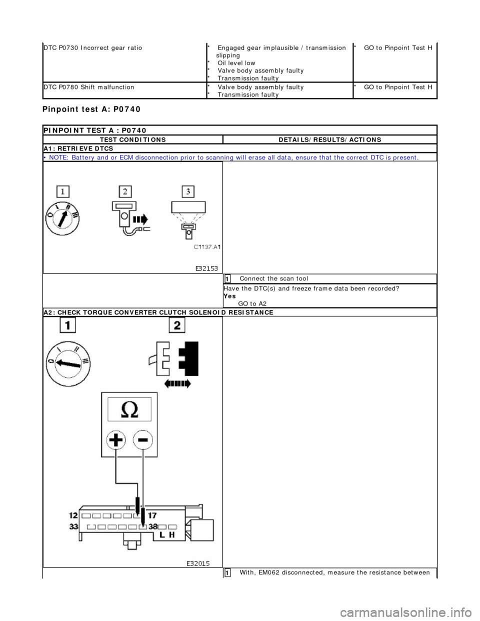
Pinpoint test A: P0740
DTC P0730 Incorrect gear ratioEngaged gear implausible / transmission
slipping Oil level low
Valve body assembly faulty
Transmission faulty
*
*
*
*GO to Pinpoint Test H *
DTC P0780 Shift malfunctionValve body assembly faulty
Transmission faulty
*
*GO to Pinpoint Test H *
PINPOINT TEST A : P0740
TEST CONDITIONSDETAILS/RESULTS/ACTIONS
A1: RETRIEVE DTCS
• NOTE: Battery and or ECM disconnection prior to scanning wi
ll erase all data, ensure that the correct DTC is present.
Connect the scan tool 1
Have the DTC(s) and freeze frame data been recorded?
Yes GO to A2
A2: CHECK TORQUE CONVERTER CLUTCH SOLENOID RESISTANCE
With, EM062 disconnected, measure the resistance between 1