1998 JAGUAR X308 Heel board
[x] Cancel search: Heel boardPage 151 of 2490

Inst
all inboard circli
p in vertical link.
5. U
sing a hydraulic press, install hub in vertical link.
1. Position special tool on press bed.
2. Position vertical link on the tool, with the inboard-side downwards.
3. Position hub to bearing.
4. Position a flat steel plate across the face of the hub,
DO NOT place plate ac ross wheel studs.
5. Operate press to install hu b in vertical link, applying
a three-ton seating load to ensure hub fully seats in
wheel bearing.
6. U
sing special tool, secure vertical link and hub assembly in a
vise.
Secure special
tool in a vise.
Posit
ion hub in tool.
Inst
all wheel nuts.
7. i
nstall rotor nut .
1. Install rotor nut on hub.
2. Using special tool tighten rotor nut to 270-330Nm.
8. CAUTION: Do not slacken the rotor nut to engage the
spring clip.
• NOTE: If the castellated slots of the rotor nut are not aligned,
Page 317 of 2490

Yes
Vehicle is OK.
No GO to J2
.
J
2: CHECK BRAKE FLUID LEVEL
Check the brake master cyli
nder reservoir fluid level.
1
Is the fl
uid level OK?
Yes GO to J3
.
No
CHECK brake master cylinder reservoir sealing points. For additional information, refer to Brake
Master Cylinder in this section. ADD brake fl uid and BLEED the brake system. For additional
information, refer to General Proc edures in this section. TEST the system for normal operation.
REPEAT road test if necessary.
J
3: CHECK BRAKE PEDAL RESERVE
Engine is
idle.
1
Apply the brake pedal ligh
tl
y three or four times.
2
W
ait 15 seconds for the vacuum to replenish.
3
Push down on
the brake pedal until it stops moving
downward or an increased resistance to the brake
pedal travel occurs.
4
Hol
d the brake pedal in the applied position while increasing the engine speed to 2000 revs/min.
5
Re
lease the accelerator pedal.
6
Does th
e brake pedal move downward as
the engine speed returns to idle?
Yes GO to J4
.
No
CHECK the vacuum to the brake booster. Fo r additional information, refer toSection 206
-0
7 Power
Brake Ac
tuation
.
J
4: CHECK THE FRONT HUB AND BEARING ASSEMBLY
Check the fr
ont hub and bearing assembly. Fo
r additional information, refer toSection 204
-01
Front
Suspe
nsion
. 1
Are th
e front wheel bearings loose?
Yes INSTALL a new front wheel bearin g if damaged. For additional information, refer toSection 204
-01
F
ront Suspension
. TEST
the system for normal operation.
No CHECK the front brake discs for thickness variances. For additional information, refer to General
Procedures in this section.
PINPO
INT TEST K : SLOW OR INCOMPLETE BRAKE PEDAL RETURN
TE
ST
CONDITIONS
D
ETAILS/RESULTS/ACTIONS
K1: C
HECK FOR BRAKE PEDAL RETURN
Ru
n the engine at fast idle while
making several brake applications.
1
Pull the
brake pedal rearward with approximately 44.5 N (10lb) force.
2
Relea
se the brake pedal and measure
the distance to the toe board.
3
Make a hard brake
application.
4
Relea
se the brake pedal and measure the brake
pedal to toe board distance. The brake pedal
should return to its original position.
5
Does th
e brake pedal return
to its original position?
Yes Vehicle is OK.
No GO to K2
.
K
2: CHECK FOR BRAKE PEDAL BINDING
Check the brake pedal to make
s
ure it is operating freely.
1
Is th
e brake pedal operating freely?
Yes INSTALL a new brake booster. For addi tional information, refer toSection 206
-0
7 Power Brake
Actuation. TEST
the system for normal operation.
No REPAIR or INSTALL new brake pedal. TE ST the system for normal operation.
Page 467 of 2490

High
-pitched sound like rubbing a clean window.
Squea
l
Continu
ous, high-pitched sound like runn
ing finger nails across a chalkboard.
Tap
Ligh
t, hammering sound like tapping pencil on edge
of table. May be rhythmic or intermittent.
Weep
Continu
ous mid-range sound (lower frequency
than squeal, higher frequency than groan).
Whir/
Whine
High
-pitched buzzing sound, like
an electric motor or drill.
Whistle
Sharp, shril
l sound, like wi
nd passing a small opening.
Description of Specific St eer
ing System Noise Types
Bel
t Squeal
Belt squea
l is a high frequency air-born
e noise generated by slippage of the ribbe d Vee belt on the power steering pump
pulley. Squeal increases with system loading and at the end of lock.
Clonk
Cl
onk is a structure-borne nois
e heard as a loose-sounding rattle or vibration coming from the steering column. Clonk can
be identified by driving and turning over cobblestones, rough roads, or high frequency bumps such as 25-50 mm tall tar
strips. Clonk requires a tie-rod load impact.
Column Knoc
k
Col
umn knock is a loose-sounding rattle or
vibration generated by the steering column shaft contacting other portions of the
column assembly. The noise is both audible and tactile. Column knock is generate d by driving over cobblestones or rough
pavement. It is not necessary to turn the steering wheel to create this noise.
Column Ra
ttle
Co
lumn rattle is a metallic sounding no
ise created when applying a highly impuls ive force to the steering wheel. Column
rattle is often used to combine the more general group of column noises includin g clonk and column knock. Column rattle
noises can be caused by clonk, knock, l oose column components, bonus parts etc. A series of parked, straight-line driving,
and cornering test should be carried out to isolate the source/sources.
Gr
inding/Scrape
Gr
inding is a low frequency noise in the column when the st
eering wheel is turned. Is generally caused by interference
between moving components such as the st eering wheel to steering column shroud.
Gr
unt (Squawk)
Grunt
is a "honking" sound elicited when coming off one of
the steering stops. Grunt is generally excited during parking
manoeuvres with a low to me dium speed steering input.
Squea
k
Page 491 of 2490

DO NOT DRIVE THE VEHICLE WITH THE TEST EQUIPMENT INSTALLED.
With the control valve CLOSED the pump maximum output pressure can be checked.
Remov
ing Test Equipment
T
o remove the test equipment:
Install a hose clamp
on the
reservoir to pump hose.
Re
moving the test equipmen
t is a reversal of the installation instructions.
Install a new O-r
ing to the PAS pump high
pressure outlet to hose connection.
Inst
all the original hose to the PAS pump.
R
emove the clamp from the reservoir to pump hose.
Top-up the reservoi
r fluid.
B
leed the PAS system; refe
r to this section.
Refer to PDU
User Guide
T
he PDU will diagnose all electrical components of the system.
Before changing a component, chec k fuse No. 12 (10A) in the left-hand heelboard fu se box. However, if this fuse is faulty a
number of other components wi ll also fail to function.
Page 1218 of 2490

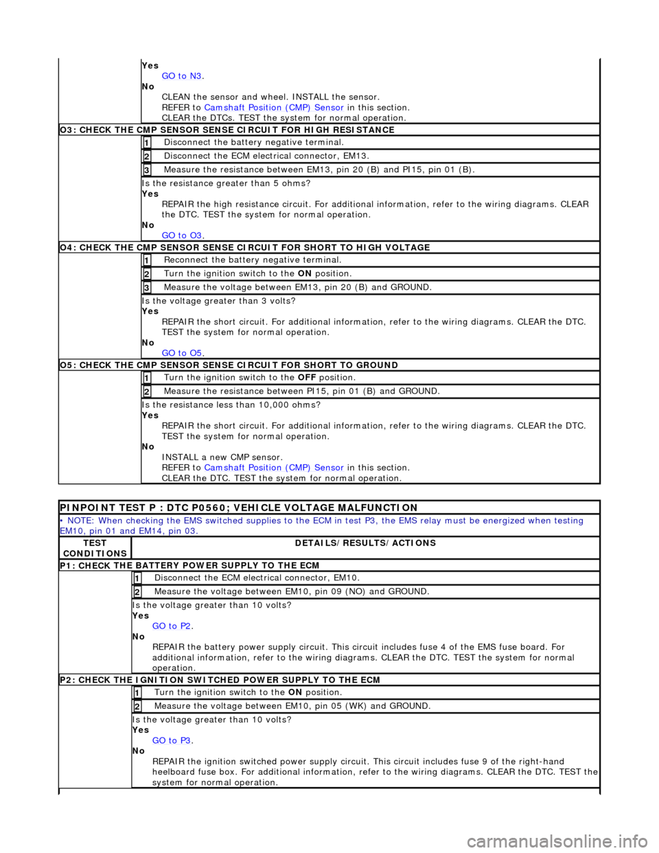
Yes
GO to N3.
No
CLEAN th
e sensor and whee
l. INSTALL the sensor.
REFER to Camshaft Position (CMP) Sensor
in this
section.
CLEAR the DTCs. TEST the system for normal operation.
O3: CHECK THE CM P SEN
SOR SENS
E CIRCUIT FOR HIGH RESISTANCE
Disc
onnect the battery negative terminal.
1
D
i
sconnect the ECM electrical connector, EM13.
2
Meas
ure t
he resistance between EM13, pin 20 (B) and PI15, pin 01 (B).
3
Is the res
istance greater than 5 ohms?
Yes REPAIR the high resistance circui t. For additional information, refer to the wiring diagrams. CLEAR
the DTC. TEST the system for normal operation.
No GO to O3
.
O4: CHECK THE CM P SEN
SOR SENSE CI
RCUIT FOR SHORT TO HIGH VOLTAGE
Re
connect the battery negative terminal.
1
Turn the ignition swi
t
ch to the ON
position.
2
Me
asure the voltage between EM13, pin 20 (B) and GROUND.
3
Is th
e volt
age greater than 3 volts?
Yes REPAIR the short circuit. For addi tional information, refer to the wiring diagrams. CLEAR the DTC.
TEST the system for normal operation.
No GO to O5
.
O5: CH ECK THE CM
P SENSOR SENSE CIRCUIT FOR SHORT TO GROUND
Turn the ignition swi
t
ch to the OFF
position.
1
Me
asure the resistance between PI15, pin 01 (B) and GROUND.
2
Is
t
he resistance less than 10,000 ohms?
Yes REPAIR the short circuit. For addi tional information, refer to the wiring diagrams. CLEAR the DTC.
TEST the system for normal operation.
No INSTALL a new CMP sensor.
REFER to Camshaft Position (CMP) Sensor
in this
section.
CLEAR the DTC. TEST the system for normal operation.
P I
NPOINT TEST P : DTC P0560; VEHICLE VOLTAGE MALFUNCTION
•
NOTE
: When checking the EMS switched supplies to the ECM
in test P3, the EMS relay must be energized when testing
EM10, pin 01 and EM14, pin 03.
TE S
T
CONDITIONS
D E
TAILS/RESULTS/ACTIONS
P1: CHECK
THE BATTERY POWER SUPPLY TO THE ECM
D
i
sconnect the ECM electrical connector, EM10.
1
Measure the
voltage between EM 10,
pin 09 (NO) and GROUND.
2
Is the vol
t
age greater than 10 volts?
Yes GO to P2
.
No
REPAIR th
e battery power supply circ
uit. This circuit includes fuse 4 of the EMS fuse board. For
additional information, refer to the wiring diagrams. CLEAR the DT C. TEST the system for normal
operation.
P2: CHECK
THE IGNITION SWITCH
ED POWER SUPPLY TO THE ECM
Turn the ignition swit
ch to the
ON position.
1
Meas
ure t
he voltage between EM10, pin 05 (WK) and GROUND.
2
Is the vol
t
age greater than 10 volts?
Yes GO to P3
.
No
REP
AIR the ignition switched power supply circuit. This circuit includes fuse 9 of the right-hand
heelboard fuse box. For a dditional information, refer to the wiri ng diagrams. CLEAR the DTC. TEST the
system for normal operation.
Page 1219 of 2490

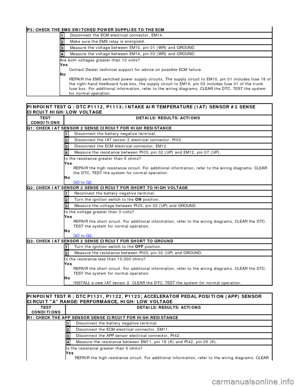
P3: CHECK
THE EMS SWITCHED
POWER SUPPLIES TO THE ECM
D
isconnect the ECM electrical connector, EM14.
1
Make sure the EMS re
lay i
s energized.
2
Meas
ure the voltage between EM10, pin 01 (WR) and GROUND.
3
Meas
ure the voltage between EM14, pin 03 (WR) and GROUND.
4
Are both
voltages greater than 10 volts?
Yes Contact Dealer technical support for advice on possible ECM failure.
No REPAIR the EMS switched power supply circuits. The su pply circuit to EM10, pin 01 includes fuse 18 of
the right-hand heelboard fuse box, the supply circuit to EM14, pin 03 includes fuse 01 of the trunk
fuse box. For additional information, refer to th e wiring diagrams. CLEAR the DTC. TEST the system
for normal operation.
PI
NPOINT TEST Q : DTC P1112, P1113; INTAKE
AIR TEMPERATURE (IAT) SENSOR #2 SENSE
CIRCUIT HIGH/LOW VOLTAGE
TE
ST
CONDITIONS
D
ETAILS/RESULTS/ACTIONS
Q1:
CHECK IAT SENSOR 2 SENSE CIRCUIT FOR HIGH RESISTANCE
Di
sconnect the battery negative terminal.
1
Di
sconnect the IAT sensor 2 electrical connector, PI03.
2
D
isconnect the ECM electrical connector, EM12.
3
Me
asure the resistance between PI03, pin 02 (UP) and EM12, pin 07 (UP).
4
Is th
e resistance greater than 5 ohms?
Yes REPAIR the high resistance circui t. For additional information, refer to the wiring diagrams. CLEAR
the DTC. TEST the system for normal operation.
No GO to Q2
.
Q2: CH
ECK IAT SENSOR 2 SENSE CIRC
UIT FOR SHORT TO HIGH VOLTAGE
R
econnect the battery negative terminal.
1
Turn the ignition swi
tch to the ON
position.
2
Measure the
voltage between PI
03, pin 02 (UP) and GROUND.
3
Is th
e voltage greater than 3 volts?
Yes REPAIR the short circuit. For addi tional information, refer to the wiring diagrams. CLEAR the DTC.
TEST the system for normal operation.
No GO to Q3
.
Q3:
CHECK IAT SENSOR 2 SENSE CIRCUIT FOR SHORT TO GROUND
Turn the ignition swi
tch to the OFF
position.
1
Meas
ure the resistance between PI03, pin 02 (UP) and GROUND.
2
Is
the resistance less than 10,000 ohms?
Yes REPAIR the short circuit. For addi tional information, refer to the wiring diagrams. CLEAR the DTC.
TEST the system for normal operation.
No INSTALL a new IAT sensor 2. CLEAR the DTC. TEST the system for normal operation.
P
INPOINT TEST R : DTC P1121, P1122, P1123;
ACCELERATOR PEDAL POSITION (APP) SENSOR
CIRCUIT "A" RANGE/PERFORMANCE, HIGH/LOW VOLTAGE
TE
ST
CONDITIONS
D
ETAILS/RESULTS/ACTIONS
R1: CHECK THE APP
SENSOR SENSE CIRCUIT FOR HIGH RESISTANCE
Di
sconnect the battery negative terminal.
1
D
isconnect the ECM electrical connector, EM11.
2
Di
sconnect the APP sensor electrical connector, PI42.
3
Meas
ure the resistance between EM11, pin 16 (K) and PI42, pin 05 (K).
4
Is th
e resistance greater than 5 ohms?
Yes REPAIR the high resistance circui t. For additional information, refer to the wiring diagrams. CLEAR
Page 1861 of 2490

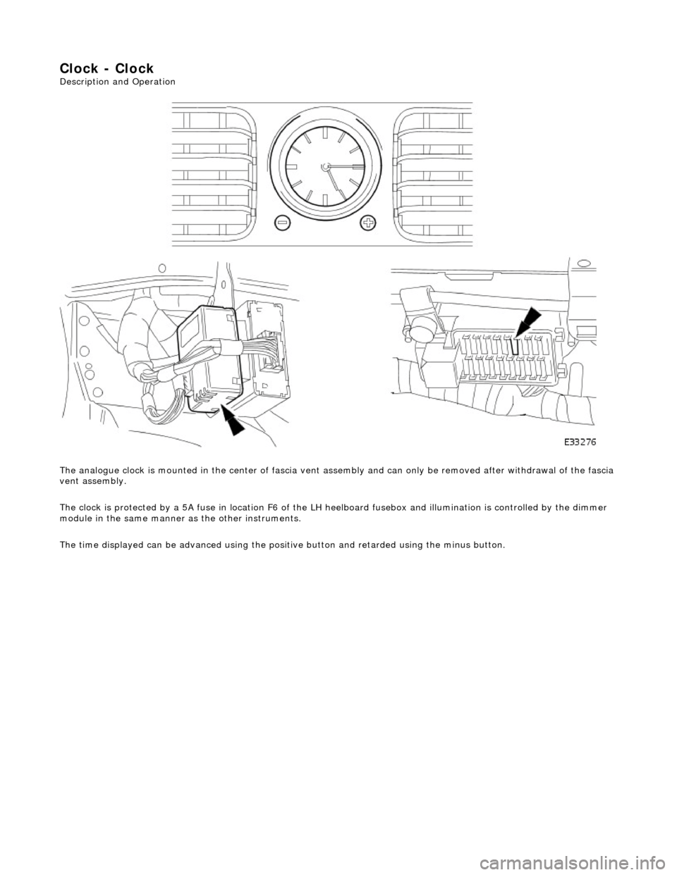
Clock - Clock
Description and Operation
The analogue clock is mounted in the center of fascia vent assembly and can only be removed after withdrawal of the fascia
vent assembly.
The clock is protected by a 5A fuse in lo cation F6 of the LH heelboard fusebox and illumination is controlled by the dimmer
module in the same manner as the other instruments.
The time displayed can be advanced using the positive button and retarded using the minus button.
Page 1963 of 2490

Rear courtesy/ reading lamps
Each rear quarter of the passenger compartment is fitted with combined lighting units comprising; a rear courtesy lamp and
reading lamp. The courtesy lamps operate automatically whenever a rear door is opened; the reading lamps function when
the integral switches are operated by occupants of the vehicle.
Trunk lamps
The trunk trim panel is fitted with lamps which operate auto matically whenever the trunk lid is opened; the switch is
incorporated within the latch mechanism.
Vanity mirror lamps
The vanity mirror lamps, two on each sun visor, operate auto matically when the mirror flap is opened, provided the sun
visor spindle is engage d in the stowage clip.
Operation
The BPM provides an enable signal for the glovebox, vanity mirror, trunk lid and map lamps. Actuation of the relevant
switch provides an earth path to the lamp.
The rear passenger reading lamps receive a supply di rect from fuse F10 in the RH heelboard fuse-box.
The front and rear courtesy lamps have separa te fade functions controlled by the BPM.
The door hazard / puddle lamps are controll ed locally by the relevant Door Module.
Fault analysis must be undertaken using the PDU, refer to Diagnosis and Testing.
Refer to the relevant Electrical Guid e for details of circuit operation.